
Operating instructions
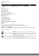
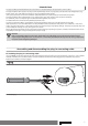
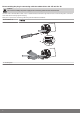

Table Of Contents
- Front cover
- Table of contents
- Contents
- General
- Warranty
- Safety instructions
- Intended use
- Assembling and disassembling the plug-in connecting cable
- Installation
- Assembling the drive
- Undoing the mounting pin
- Drive adapter for obstacle detection
- Assembling the drive adapter with drive adapter safety catch
- Assembling the drive adapter with screw connection
- Securing the drive against axial displacement
- Fixing the drive adapter to the barrel dia. 45
- Mounting the drive in the tube
- Confirming the drive
- First operation
- Programming the master transmitter
- Checking that the running direction is correct
- Intelligent installation management
- Setting the limit positions
- Changing the set limit positions
- Deleting the limit positions
- Intermediate positions I + II
- Programming additional transmitters
- Deleting transmitters
- Overwriting the master
- Upper anti-freeze mechanism
- Obstacle detection
- Fly screen protection function
- Programming the run times
- Deleting the run times
- Disposal
- Maintenance
- Technical data dia. 45
- What to do if...?
- Sample wiring diagram
- Declaration of conformity
- Last page
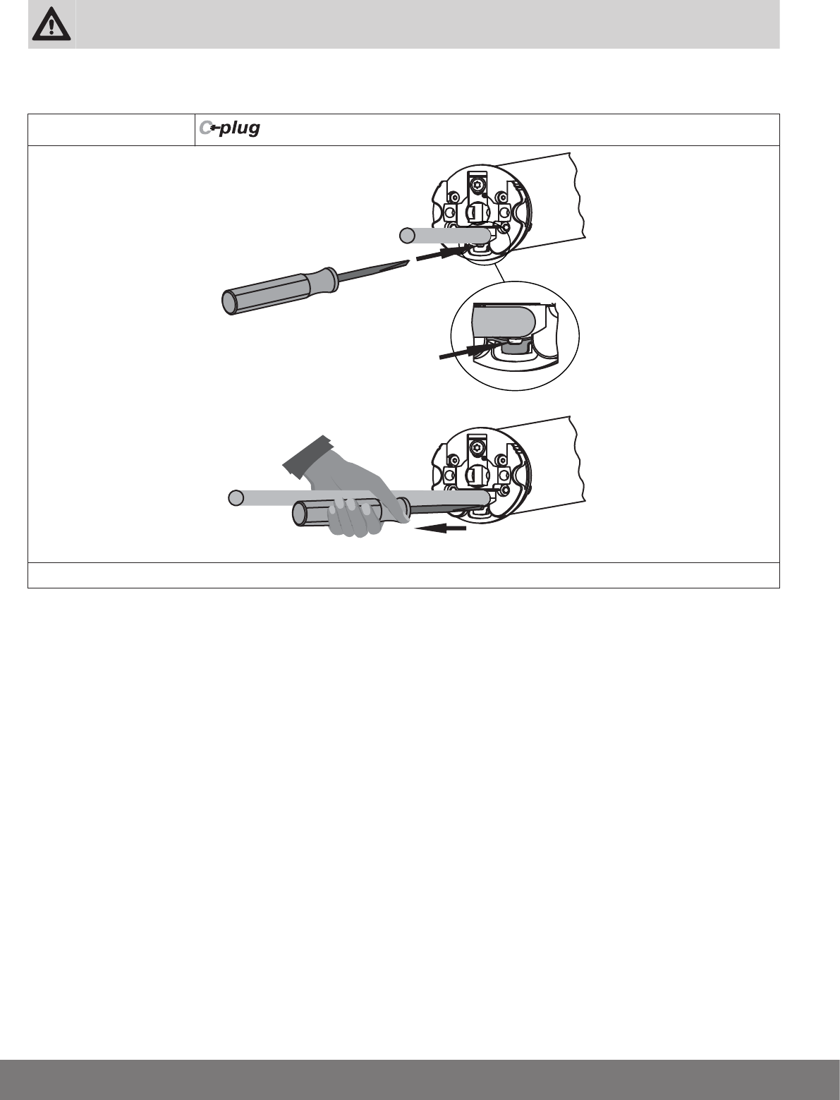
Disassembling the plug-in connecting cable for tubular drives dia. 45 and dia. 58
Caution
Prior to disassembly, the power supply to the connecting cable must be disconnected.
On drives with a diameter Ø45 or Ø58, insert a suitable flathead screwdriver right into the recess of the locating latch, so that the
latch releases the locating lug from the plug.
Now you can pull out the connecting cable along with the flathead screwdriver.
dia. 45 and dia. 58
2.
1.
A
A = locating latch
8