
Operating instructions
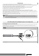
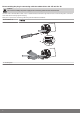
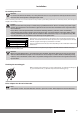

Table Of Contents
- Front cover
- Table of contents
- Contents
- General
- Warranty
- Safety instructions
- Intended use
- Assembling and disassembling the plug-in connecting cable
- Installation
- Assembling the drive
- Undoing the mounting pin
- Drive adapter for obstacle detection
- Assembling the drive adapter with drive adapter safety catch
- Assembling the drive adapter with screw connection
- Securing the drive against axial displacement
- Fixing the drive adapter to the barrel dia. 45
- Mounting the drive in the tube
- Confirming the drive
- First operation
- Programming the master transmitter
- Checking that the running direction is correct
- Intelligent installation management
- Setting the limit positions
- Changing the set limit positions
- Deleting the limit positions
- Intermediate positions I + II
- Programming additional transmitters
- Deleting transmitters
- Overwriting the master
- Upper anti-freeze mechanism
- Obstacle detection
- Fly screen protection function
- Programming the run times
- Deleting the run times
- Disposal
- Maintenance
- Technical data dia. 45
- What to do if...?
- Sample wiring diagram
- Declaration of conformity
- Last page
Explanation of nomenclature
Tubular drives:
Example: R12/17C PROF+
R 12 / 17 C PROF+
Type Nm
min
-1
C-Plug =
plug-in connecting cable
Limit switch version
Types:
P = pico tube dia. 35 mm
R = regular tube dia. 45 mm
L = large tube dia. 58 mm
Limit switching versions:
M= mechanical limit switch
HK = mechanical limit switch with crank
G = DC drives with mechanical limit switch
GHK = DC drives with mechanical limit switch and crank
Electronic limit switching:
R= roller shutters
S = sun protection
F = with integrated radio receiver
P = with point-to-point switching
E = reversing in the limit position
O = with sensitive obstacle detection
SMI = Standard Motor Interface
+ (with R) = with automatic detection of anti-lifting devices
+ (with S) = higher closing force for cassette awnings
Software versions
A0…z9
The date of manufacture comes from the first four digits of the serial number.
The numbers 1 and 2 indicate the year and the numbers 3 and 4 indicate the calendar week.
Example: 24th calendar week in 2012
Ser. No.: 1224XXXXX
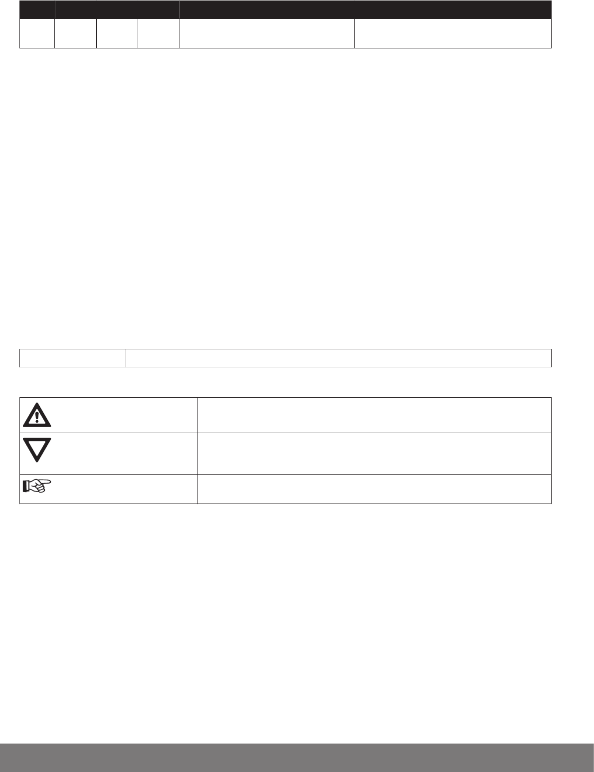
Explanation of pictograms
Caution
Denotes a potentially hazardous situation. If this is not avoided, injuries may result.
Attention
Denotes a potentially hazardous situation. If this is not avoided, the product or some‐
thing in its vicinity may be damaged.
Note
Denotes user tips and other useful information.
4