
Operating instructions
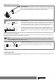
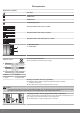
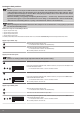
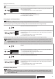
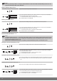
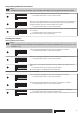
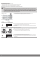
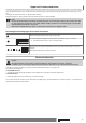
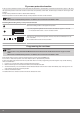
Table Of Contents
- Front cover
- Table of contents
- Contents
- General
- Warranty
- Safety instructions
- Intended use
- Assembling and disassembling the plug-in connecting cable
- Installation
- Assembling the drive
- Undoing the mounting pin
- Drive adapter for obstacle detection
- Assembling the drive adapter with drive adapter safety catch
- Assembling the drive adapter with screw connection
- Securing the drive against axial displacement
- Fixing the drive adapter to the barrel dia. 45
- Mounting the drive in the tube
- Confirming the drive
- First operation
- Programming the master transmitter
- Checking that the running direction is correct
- Intelligent installation management
- Setting the limit positions
- Changing the set limit positions
- Deleting the limit positions
- Intermediate positions I + II
- Programming additional transmitters
- Deleting transmitters
- Overwriting the master
- Upper anti-freeze mechanism
- Obstacle detection
- Fly screen protection function
- Programming the run times
- Deleting the run times
- Disposal
- Maintenance
- Technical data dia. 45
- What to do if...?
- Sample wiring diagram
- Declaration of conformity
- Last page
Setting the limit positions
Note
The limit positions can only be set with the master transmitter. The shutter direction must be correct. When
setting the limit positions, the tubular drive runs in dead-man mode and limit position status indicator. The up‐
per limit position must always be set first. When setting the upper limit position, ensure that the roller shutter
curtain is not pulled out of the guide tracks.
When first installing, using springs and adjusting the limit position ‘...to lower stop’, the barrel in the lower lim‐
it position turns approx. 1/4 of a turn further than usual. In doing so, the tubular drive is able to automatically
detect the use of anti-lifting devices or springs. The tubular drive switches off automatically.
Attention
When operating the tubular drive without the drive adapter for obstacle detection, if using springs a point must
be set in the lower limit position.
There are 4 ways to set the limit positions:
▪ Upper stop to lower stop
▪ Upper point to lower point
▪ Upper stop to lower point
▪ Upper point to lower stop
The limit position becomes fixed after the tubular drive has turned off automatically in the desired position three times.
Upper stop to lower stop
Open to the permanent upper stop.
[ The tubular drive switches off automatically.
Then close to the permanent lower stop.
[ The tubular drive switches off automatically.
Æ The limit positions are now set.
Upper point to lower point
Note
There is no shading solution length adjustment with this limit position setting.
Open to the desired upper limit position.
Press the programming button and, within 3 seconds, also press the UP button and
hold the two buttons down.
[ The tubular drive makes a “click” sound to confirm.
Then close to the desired lower limit position.
Press the programming button and, within 3 seconds, also press the DOWN button
and hold the two buttons down.
[ The tubular drive makes a “click” sound to confirm.
Æ The limit positions are now set.
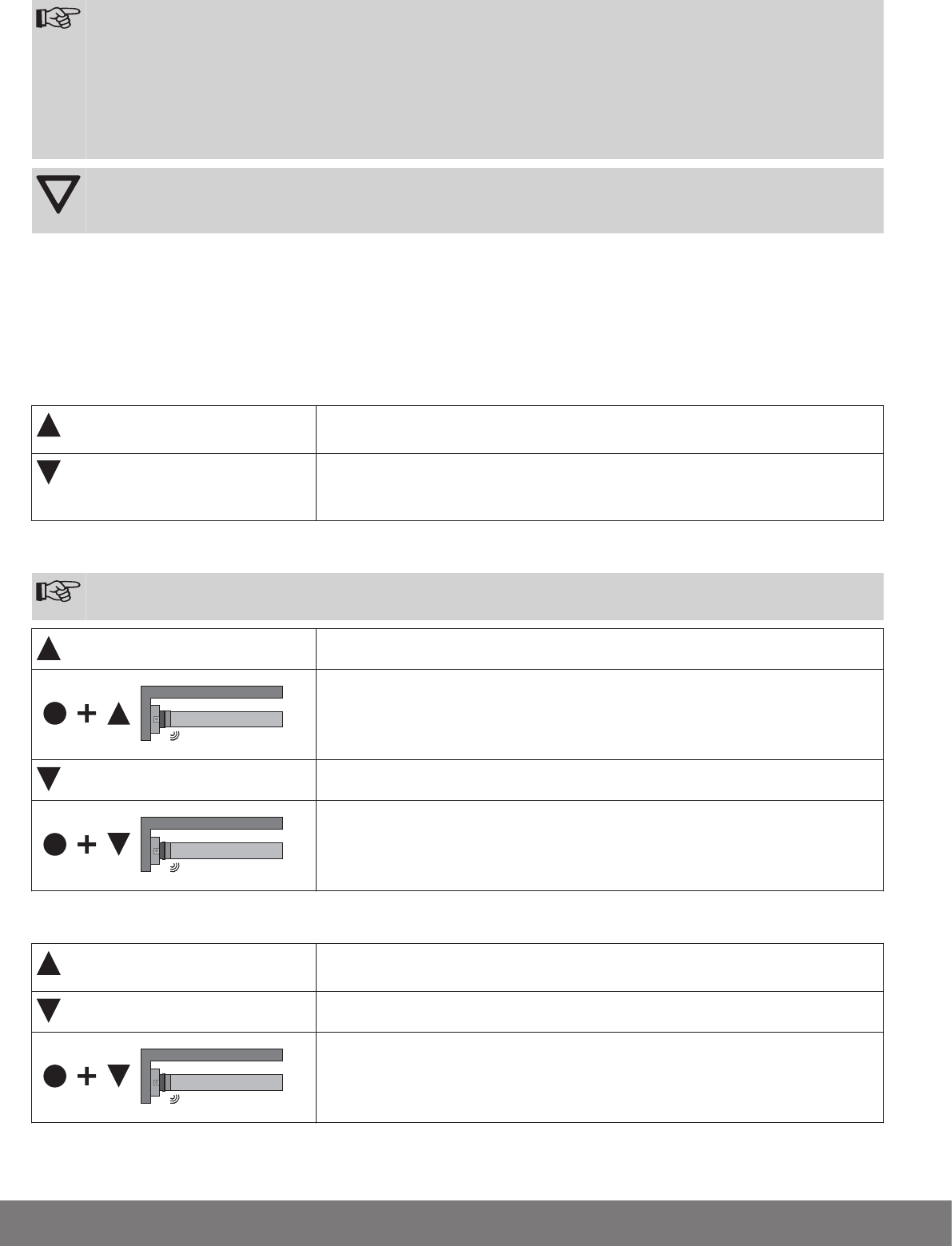
Upper stop to lower point
Open to the permanent upper stop.
[ The tubular drive switches off automatically.
Then close to the desired lower limit position.
Press the programming button and, within 3 seconds, also press the DOWN button
and hold the two buttons down.
[ The tubular drive makes a “click” sound to confirm.
Æ The limit positions are now set.
14