
Operating instructions
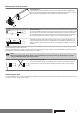
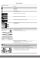
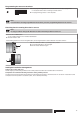
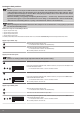
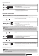
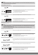
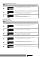
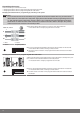
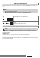
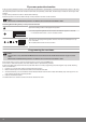
Table Of Contents
- Front cover
- Table of contents
- Contents
- General
- Warranty
- Safety instructions
- Intended use
- Assembling and disassembling the plug-in connecting cable
- Installation
- Assembling the drive
- Undoing the mounting pin
- Drive adapter for obstacle detection
- Assembling the drive adapter with drive adapter safety catch
- Assembling the drive adapter with screw connection
- Securing the drive against axial displacement
- Fixing the drive adapter to the barrel dia. 45
- Mounting the drive in the tube
- Confirming the drive
- First operation
- Programming the master transmitter
- Checking that the running direction is correct
- Intelligent installation management
- Setting the limit positions
- Changing the set limit positions
- Deleting the limit positions
- Intermediate positions I + II
- Programming additional transmitters
- Deleting transmitters
- Overwriting the master
- Upper anti-freeze mechanism
- Obstacle detection
- Fly screen protection function
- Programming the run times
- Deleting the run times
- Disposal
- Maintenance
- Technical data dia. 45
- What to do if...?
- Sample wiring diagram
- Declaration of conformity
- Last page
Mounting the drive in the tube
For profile tubes:
In the case of some drive adapters, tolerances of the groove widths in different bar‐
rels can be offset by rotating the drive adapter into a different groove recess. These
groove recesses have different sizes and allow the drive to fit exactly.
For round tubes:
First notch the tube on the motor side, so the lug of the thrust ring can also be pushed
into the tube. There must be no play between the lug of the thrust ring and the tube.
For rings without drive lugs, which are used to assist fitting on the thrust ring, the bar‐
rel must be connected to the thrust ring by a 4.8 x 9.5 mm self-tapping screw.
Assemble the tubular drive with the relevant thrust ring (1) and drive adapter (2). In‐
sert the tubular drive with the pre-assembled thrust ring and drive adapter into the
tube to achieve a form fit. Ensure that the thrust ring and drive adapter are secure in
the tube.
Mount the assembled unit comprising barrel, tubular drive and idler on the box and secure the drive according to the type of wall
bracket fixing with a split or spring pin.
After programming the transmitter, position the barrel so that the roller shutter curtain can be mounted with springs or fit the anti-
lifting device in accordance with the manufacturer's instructions.
Note
When using springs/anti-lifting devices, we recommend you use at least three; for longer tubes, use three
springs/anti-lifting devices per meter of barrel.
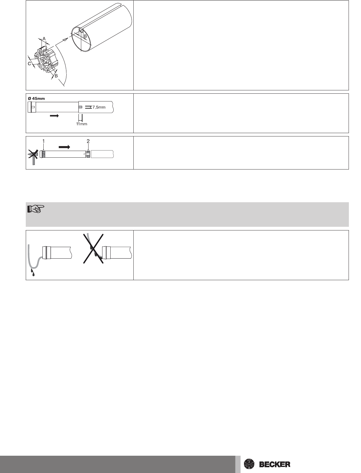
Lay the connecting cable
Lay the connecting cable up to the tubular drive, and fix The connecting cable and
any antennae must not project into the winding chamber. Cover any sharp edges.
Confirming the drive
The drive audibly confirms each programming and deletion action. The tubular drive makes a barely perceptible movement, which
you hear as a “click" or "click click" sound.
11