R12/17C...R40/17C Version: PROF+A2 en Assembly and Operating Instructions Roller shutter drive with integrated radio receiver 915.3 Mhz Important information for: • Fitters / • Electricians / • Users Please forward accordingly! These instructions must be kept safe for future reference. Becker-Antriebe GmbH Friedrich-Ebert-Straße 2-4 35764 Sinn/Germany www.becker-antriebe.
Table of contents Contents ............................................................................................................................................................................. 3 General .............................................................................................................................................................................. 3 Warranty ...................................................................................................................
Contents General These tubular drives are high-quality products with the following features: ▪ Optimised for roller shutter operation ▪ Individual, group and central radio control ▪ No need to run wires to a switch or relay control device ▪ Any combination of drive and transmitter possible ▪ Simple to set the limit positions with the transmitter ▪ Installation without stops possible (from upper point to lower point) ▪ Two freely selectable intermediate positions can be set ▪ Flexible radio grouping; can be
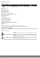
Explanation of nomenclature Tubular drives: Example: R12/17C PROF+ R Type 12 / 17 Nm min -1 C C-Plug = plug-in connecting cable PROF+ Limit switch version Types: P = pico tube dia. 35 mm R = regular tube dia. 45 mm L = large tube dia.
Warranty Structural modifications and incorrect installation which are not in accordance with these and our other instructions can result in serious injuries, e.g., crushing of limbs. Therefore, structural modifications may only be carried out with our prior approval and strictly in accordance with our instructions, particularly the information contained in these Assembly and Operating Instructions. Any further processing of the products which does not comply with their intended use is not permitted.
Caution Important safety instructions for installation and commissioning Failure to observe these instructions can lead to serious injuries. ▪ Observe the safety instructions in EN 60335-2-97. Please note that this list of safety instructions is not ex‐ haustive, since it would be impossible for the standard to include all sources of danger.
Intended use The type of tubular drive described in these instructions is intended solely for the operation of roller shutters. This type of tubular drive supports not only curtain attachment by means of springs but also mechanical anti-lifting devices (e.g., Zurfluh-Feller, Simu, GAH Alberts and Deprat). These are detected automatically. If the springs or the top lath are not screwed or rivetted to the barrel, a point must be set in the lower limit position.
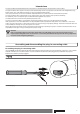
Disassembling the plug-in connecting cable for tubular drives dia. 45 and dia. 58 Caution Prior to disassembly, the power supply to the connecting cable must be disconnected. On drives with a diameter Ø45 or Ø58, insert a suitable flathead screwdriver right into the recess of the locating latch, so that the latch releases the locating lug from the plug. Now you can pull out the connecting cable along with the flathead screwdriver. dia. 45 and dia. 58 1. A 2.
Installation Assembling the drive Attention To connect the drive to the driven part, solely mechanical accessory components made by the drive manufac‐ turer from the current product catalogue may be used. Prior to mounting, the fitter must ensure that the masonry and the system being motorised are sufficiently robust (drive torque plus weight of the shading solution). Caution Electrical connections may only be carried out by a qualified electrician.
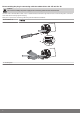
Assembling the drive adapter with drive adapter safety catch Put the drive adapter (1) onto the drive shaft of the tubular drive. You can see which way to insert the safety catch (2) from its shape. When inserting the drive adapter safety catch (2) into the hole (4), make sure that the locking lug (3) engages. You will hear a click. Check that the safety catch is securely in position by pulling on the drive adapter (1).
Mounting the drive in the tube For profile tubes: In the case of some drive adapters, tolerances of the groove widths in different bar‐ rels can be offset by rotating the drive adapter into a different groove recess. These groove recesses have different sizes and allow the drive to fit exactly. For round tubes: First notch the tube on the motor side, so the lug of the thrust ring can also be pushed into the tube. There must be no play between the lug of the thrust ring and the tube.
First operation Explanation of symbols UP button STOP button DOWN button Programming button The tubular drive clicks once to confirm The tubular drive clicks twice to confirm The tubular drive clicks three times to confirm 1 = direction switch 2 = radio switch Connecting the tubular drive Connect the tubular drive to the power supply.
Programming the master transmitter Press the programming button for 3 seconds when it is ready to programme. [ The tubular drive makes a clicking sound to confirm. Æ The programming process is now complete. Note If a transmitter is already programmed on the receiver, press the programming button for 10 seconds. Checking that the running direction is correct Note It is only possible to change the direction of rotation if no limit position has been set.
Setting the limit positions Note The limit positions can only be set with the master transmitter. The shutter direction must be correct. When setting the limit positions, the tubular drive runs in dead-man mode and limit position status indicator. The up‐ per limit position must always be set first. When setting the upper limit position, ensure that the roller shutter curtain is not pulled out of the guide tracks. When first installing, using springs and adjusting the limit position ‘...
Upper point to lower stop Open to the desired upper limit position. Press the programming button and, within 3 seconds, also press the UP button and hold the two buttons down. [ The tubular drive makes a “click” sound to confirm. Then close to the permanent lower stop. [ The tubular drive switches off automatically. Æ The limit positions are now set. Changing the set limit positions Note Once set, the limit positions can only be changed with the master transmitter.
Note Once set, the limit positions can only be deleted with the master transmitter. Deleted limit positions are dis‐ played on the limit position status indicator. Deleting individual limit positions Open/close to the limit position to be deleted. Press the programming button and, within 3 seconds, also press the STOP button and hold the two buttons down for 10 seconds. [ The tubular drive makes a clicking sound to confirm. Æ The limit position is now deleted.
Programming additional transmitters Note In addition to the master transmitter, up to 15 further transmitters can be programmed in the tubular drive. Press the programming button of the master transmitter for 3 seconds. [ The tubular drive makes a “click” sound to confirm. Now press the programming button of a new transmitter which has not yet been pro‐ grammed in the tubular drive for 3 seconds. Doing so activates the programming mode of the tubular drive for a new transmitter for 3 minutes.
Overwriting the master There are two ways to overwrite the master: ▪ Readying the tubular drive for programming by switching on the power ▪ Readying the tubular drive for programming with the radio switch Readying the tubular drive for programming by switching on the power Note To ensure that the new master transmitter is programmed in the desired tubular drive only, all other tubular drives which are connected to the same power supply must be deactivated from the programming mode.
Upper anti-freeze mechanism The upper anti-freeze mechanism helps to prevent the roller shutter from freezing in the upper limit position, as the roller shutter stops just before the upper stop. The distance from the upper stop is automatically cyclically checked and, if necessary, correc‐ ted. The upper anti-freeze mechanism is deactivated on delivery. Both limit positions must be set before the anti-freeze mechanism can be activated.
Fly screen protection function If the fly screen protection function is activated, obstacle detection is activated after a revolution of the barrel of approx. 140° from the upper limit position. If the roller shutter curtain meets an opened fly screen door, the drive stops and returns to the upper limit position. The fly screen protection function is deactivated on delivery. Both limit positions must be set before the fly screen protection function can be activated.
Deleting the run times Note When deleting, both run times are always deleted. To delete the UP and DOWN run time, press the STOP button for 10 seconds. The tubular drive makes a "click click" sound to confirm. The run times are now deleted. Disposal This product is made of various materials which must be disposed of properly. Find out about the applicable regulations on recy‐ cling or disposal for this product in your country. The packaging material must be disposed of properly.
What to do if...? Problem Tubular drive is not functioning. Cause Remedy No transmitter programmed. Programme new transmitter. Transmitter is out of range of the tubular drive. Bring transmitter within range of the tubu‐ lar drive. Transmitter was operated out of range several times. Press drive or stop button on transmitter at least 5 times in the immediate vicinity of the tubular drive. Batteries in transmitter not inserted/ in‐ serted incorrectly or dead.
Green/yellow Blue Brown Black Electronics Sample wiring diagram L N PE 23
Declaration of conformity 24
2010 300 570 0a 06/03/2013