R12/17 - L120/11 Version: HK en Assembly and Operating Instructions Tubular drives with crank handle activation Important information for: • Fitters / • Electricians / • Users Please forward accordingly! These instructions must be kept safe for future reference. Becker-Antriebe GmbH Friedrich-Ebert-Straße 2-4 35764 Sinn/Germany www.becker-antriebe.
Assembly and Operating Instructions Table of contents Contents ............................................................................................................................................................................. 3 General .............................................................................................................................................................................. 3 Warranty ..............................................................................
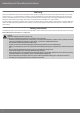
Contents General These tubular drives are high-quality products with the following features: ▪ For use with roller shutters ▪ For use with sunblinds ▪ For use with doors ▪ Convenient manual control in the event of power failure ▪ Easy limit switch setting on the drive ▪ Compatible with all of the drive manufacturer's control units for roller shutters and sunblinds. Please observe these Assembly and Operating Instructions when installing and setting the equipment.
Assembly and Operating Instructions Warranty Structural modifications and incorrect installation which are not in accordance with these and our other instructions can result in serious injuries, e.g., crushing of limbs. Therefore, structural modifications may only be carried out with our prior approval and strictly in accordance with our instructions, particularly the information contained in these Assembly and Operating Instructions.
Caution Important safety instructions for installation and commissioning Failure to observe these instructions can lead to serious injuries. ▪ Observe the safety instructions in EN 60335-2-97. Please note that this list of safety instructions is not ex‐ haustive, since it would be impossible for the standard to include all sources of danger.
Assembly and Operating Instructions Intended use The type of tubular drive described in these instructions is intended solely for the operation of roller shutters, roller doors and sun protection systems. The crank handle is intended to be used for convenient manual operation only in the event of a power fail‐ ure. Continuous operation or use of tools (e.g.
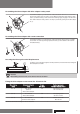
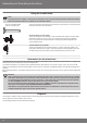
Assembling the drive adapter with drive adapter safety catch Put the drive adapter (1) onto the drive shaft of the tubular drive. You can see where to insert the safety catch (2) from its shape. When inserting the drive adapter safety catch (2) into the hole (4), make sure that the locking lug (3) engages. You will hear a click. Check that the safety catch is securely in position by pulling on the drive adapt‐ er (1).
Assembly and Operating Instructions Attention Do not hammer or drop the tubular drive into the barrel! The curtain can only be secured using springs or antilifting devices. Mounting the drive in the tube For profile tubes: In the case of some drive adapters, tolerances of the groove widths in different bar‐ rels can be offset by rotating the drive adapter into a different groove recess. These groove recesses have different sizes and allow the drive to fit exactly.
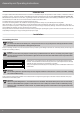
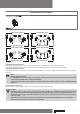
Setting the limit positions Setting tool The setting tool (Item no. 4933 300 019 0) can be used to set the limit positions. Upper limit position Lower limit position Lower limit position Upper limit position Lower limit position Upper limit position Upper limit position Lower limit position Setting the lower limit position 1.Before the shading solution is fixed to the barrel, let the drive run DOWN until it switches off automatically. 2.
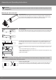
Assembly and Operating Instructions Using the crank handle Note For problem-free assembly, use mechanical and electrical accessories made by the drive manufacturer which have been tested and which are suitable for use with these drives. For 7 mm hexagonal tube and 8 mm square tube The crank handle is to be used only in the event of a power failure. It must be ensured that the limit positions are not overrun.
Technical data dia. 45 Type R12/17 HK R15/17 HK R20/17 HK R25/17 HK Rated torque (Nm) 12 15 20 25 Output speed (rpm) 17 17 17 17 Limit switch range 38 revolutions Supply voltage 230 V AC / 50 Hz Connected load (W) 110 140 160 175 Rated current consumption (A) 0.50 0.65 0.75 0.80 Mode S2 4 min Degree of protection IP 44 Min.
Assembly and Operating Instructions Type L70/17 HK L80/11 HK L80/17 HK* L120/11 HK Rated torque (Nm) 70 80 80 120 Output speed (rpm) 17 11 17 11 Limit switch range 38 revolutions Supply voltage 230 V AC / 50 Hz Connected load (W) 430 310 470 435 Rated current consumption (A) 1.90 1.40 2.10 1.90 Mode S2 4 min Degree of protection IP 44 Min. tube inside diameter (mm) 60 *) This tubular drive is not yet available. What to do if...
Sample wiring diagrams green/yellow blue brown black Operation with single switch 230 V PE N L1 Single switch 13
Assembly and Operating Instructions Central, group and individual control using Centronic UnitControl UC42 Mains 230 V / 50 Hz Control unit Central Central cable (connection to further control units) 230 V / 50 Hz Group 230 V / 50 Hz Individual 230 V / 50 Hz 230 V / 50 Hz Electronics Individual 14
Declaration of conformity 15
2010 300 231 0d 28/02/2012