
User Manual


element14 is a trademark of Premier Farnell plc 95
© 2014 Premier Farnell plc. All Rights Reserved
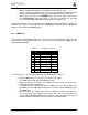
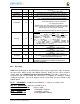
Version
38
4
Hardware version code for board in ASCII. Version format is up to the
developer.
i
.
e
.
0
2
.
1
…
0
0
A1
..
.
.
1
0
A
0
Manufacturer
42
16
ASCII name of the manufacturer. Company or individual’s name.
Part Number
58
16
ASCII Characters for the part number. Up to maker of the board.
Number of Pins
74
2
Number of pins used by the daughter board including the power pins
used.
D
ec
i
m
a
l
va
l
u
e
o
f
t
o
ta
l
p
i
n
s
9
2
m
a
x
,
s
t
o
red
i
n
H
E
X
.
Serial Number
76
12
Serial number of the board. This is a 12 character string which is:
WWYY&&&&nnnn
where: WW = 2 digit week of the year of production
YY = 2 digit year of production
&&&&=Assembly code to let the manufacturer document the assembly
number or product. A way to quickly tell from reading the serial number
what the board is. Up to the developer to determine.
nnnn = incrementing board number for that week of production
Pin Usage
88
148
Two bytes
for each configurable pins of the 74 pins on the expansion
connectors MSB LSB
Bit order: 15 14 ……………1..0
Bit 15…………..Pin is used or not……..…...0=Unused by cape 1=Used by
cape Bit 14-13………Pin Direction…………...….1 0=Output 01=Input
11=BDIR Bits 12-7………Reserved……………………should be all zeros
Bit 6……….…..Slew Rate …………………..0=Fast 1=Slow
Bit 5…….……..Rx Enable…………………..0=Disabled 1=Enabled Bit
4……….…..Pull Up/Dn Select…………..0=Pulldown 1=PullUp Bit
3…………...Pull Up/DN enabled………..0=Enabled 1=Disabled Bits 2-
0
……….Mux Mode Selection………..Mode 0-7
VDD_3V3B Current
236
2
Maximum current in milliamps. This is HEX value of the current in
decimal
1
50
0
m
A
=
0
x
0
5
0
xD
C
32
5
m
A
=
0
x
0
1
0
x4
5
VDD_5V Current
238
2
Maximum current in milliamps. This is HEX value of the current in
decimal
1
50
0
m
A
=
0
x
0
5
0
xD
C
32
5
m
A
=
0
x
0
1
0
x4
5
SYS_5V Current
240
2
Maximum current in milliamps. This is HEX value of the current in
decimal
1
50
0
m
A
=
0
x
0
5
0
xD
C
32
5
m
A
=
0
x
0
1
0
x4
5
DC Supplied
242
2
Indicates whether or not the board is supplying voltage on the VDD_5V
rail and the current rating 000=No 1-0xFFFF is the current supplied
storing the decimal equivalent in HEX format
Available 244 32543 Available space for other non-volatile codes/data to be used as
needed by the manufacturer or SW driver. Could also store
p
re
s
e
ts f
o
r
u
s
e
b
y
S
W
.
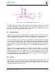
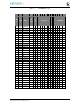
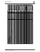
8.2.5 Pin Usage
Table 17
is the locations in the EEPROM to set the I/O pin usage for the cape. It contains
the value to be written to the Pad Control Registers. Details on this can be found in
section
9.2.2
of the
AM3358 Technical Reference Manual
, The table is left blank as a
convenience and can be printed out and used as a template for creating a custom
setting for each cape. The 16 bit integers and all 16 bit fields are to be stored in Big
Endian format.
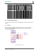
Bit 15 PIN USAGE
is an indicator and should be a 1 if the pin is used or 0 if it is
unused.
Bits 14-7 RESERVED
is not to be used and left as 0.
Bit 6 SLEW CONTROL
0=Fast 1=Slow
Bit 5 RX Enabled
0=Disabled 1=Enabled
Bit 4 PU/PD
0=Pulldown 1=Pullup.
Bit 3 PULLUP/DN
0=Pullup/pulldown enabled