
User Manual

element14 is a trademark of Premier Farnell plc 91
© 2014 Premier Farnell plc. All Rights Reserved
•
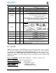
When used for other functions, the HDMI framer cannot be used.
•
There is no way to power off the framer as this would result in the framer
being powered through these input pins which would not a be a good idea.
•
These pins are also the
SYSBOOT
pins. DO NOT drive them before
the
SYS_RESETN
signal goes high. If you do, the board may not boot
because you would be changing the boot order of the processor.
In order to use these pins, the SW will need to reconfigure them to whatever function you
need the pins to do. To keep power low, the HDMI framer should be put in a low power
mode via the SW using the
I2C0
interface.
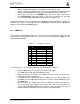
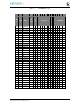
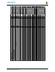
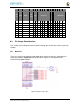
8.1.2 eMMC Pins
The element14 BeagleBone Black uses 10 pins to connect to the processor that also
connect to the P8 expansion connector. These signals are listed below in
Table 15
. The
proper mode is MODE2.
Table 15
P8 eMMC Conflict Pins
P
IN
P
RO
C
S
I
G
N
A
L
M
ODE
22 V8 MMC1_DAT5
1
23 U8 MMC1_DAT4
1
24 V7 MMC1_DAT1
1
5
R8 MMC1_DAT2
1
4
T9 MMC1_DAT7
1
3
R9 MMC1_DAT6
1
6
T8 MMC1_DAT3
1
25 U7 MMC1_DAT0
1
20 V9 MMC1_CMD 2
21 U9 MMC1_CLK 2
If using these pins, several things need to be kept in mind when doing so:
•
On the eMMC device, these signals are inputs and outputs.
•
The eMMC device will add a load onto these pins.
•
When used for other functions, the eMMC cannot be used. This means you
must boot from the microSD slot.
•
If using these pins, you need to put the eMMC into reset. This requires that
the eMMC be accessible from the processor in order to set the eMMC to accept
the eMMC pins.
•
DO NOT drive the eMMC pins until the eMMC has been put into reset.
This means that if you choose to use these pins, they must not drive any
signal until enabled via Software. This requires a buffer or some other form of
hold off function enabled by a GPIO pin on the expansion header.