
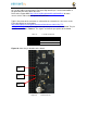
User Manual

element14 is a trademark of Premier Farnell plc 89
© 2014 Premier Farnell plc. All Rights Reserved
8.0 Cape Board Support
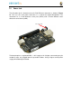
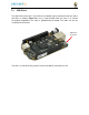
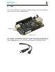
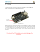
The element14 BeagleBone Black has the ability to accept up to four expansion boards or
capes that can be stacked onto the expansion headers. The word cape comes from the
shape of the board as it is fitted around the Ethernet connector on the main board. This
notch acts as a key to ensure proper orientation of the cape.
This section describes the rules for creating capes to ensure proper operation with the
element14 BeagleBone Black and proper interoperability with other capes that are
intended to co- exist with each other. Co-existence is not a requirement and is in itself,
something that is impossible to control or administer. But, people will be able to create
capes that operate with other capes that are already available based on public information
as it pertains to what pins and features each cape uses. This information will be able to be
read from the EEPROM on each cape.
This section is intended as a guideline for those wanting to create their own capes. Its
intent is not to put limits on the creation of capes and what they can do, but to set a few
basic rules that will allow the SW to administer their operation with the element14
BeagleBone Black. For this reason there is a lot of flexibility in the specification that we
hope most people will find liberating and in the spirit of Open Source Hardware. I am sure
there are others that would like to see tighter control, more details, more rules and
much more order to the way capes are handled.
Over time, this specification will change and be updated, so please refer to the latest
version of this manual prior to designing your own capes to get the latest information.
DO NOT APPLY VOLTAGE TO ANY I/O PIN
WHEN
POWER IS
NOT SUPPLIED TO THE BOARD. IT
WILL
DAMAGE THE
PROCESSOR AND VOID
THE WARRANTY.
NO PINS ARE TO BE DRIVEN UNTIL AFTER
THE
SYS_RESET
LINE GOES
HIGH.