
User Manual
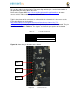

Pin 1 of the cable is the black wire. That must align with the pin 1 on the board which is
designated by the white dot on the PCB.
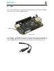
Refer to the support WIKI http://elinux.org/Beagleboard:BeagleBoneBlack for more
sources of this cable and other options that will work.
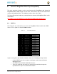
Table is the pinout of the connector as reflected in the schematic. It is the same as the
FTDI cable which can be found at
http://www.ftdichip.com/Support/Documents/DataSheets/Cables/DS_TTL-
232R_CABLES.pdf with the exception that only three pins are used on the board. The pin
numbers are defined in
Table 13
. The signals are from the perspective of the board.
Table 13
J1 Serial Header Pins
PIN NUMBER SIGNAL
1
Ground
4
R
ece
ive
5
T
ra
nsm
i
t
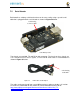
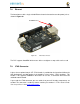
Figure 56
shows the pin location on the board.
PIN 1
PIN 4
PIN 5
Figure 56 Serial connector