
User Manual
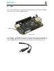

7.5 Serial Header
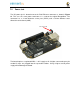
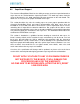
Each board has a debug serial interface that can be accessed by using a special serial
cable that is plugged into the serial header as shown in
Figure 54
below.
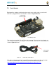
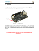
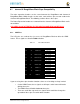
Two signals are provided, TX and RX on this connector. The levels on these signals are
3.3V. In order to access these signals, a FTDI USB to Serial cable is recommended as
shown in
Figure 55
below.
The cable can be purchased from several different places and must be the 3.3V version
TTL-232R-3V3
. Information on the cable itself can be found direct from FTDI at:
http://www.ftdichip.com/Support/Documents/DataSheets/Cables/DS_TTL-
232R_CABLES.pdf
Serial Debug
Connector Pin 1
Serial Debug
Cable Pin 1
Figure 54 Serial Debug Header
Figure 55 FTDI USB to Serial Adapter