
User Manual

element14 is a trademark of Premier Farnell plc 76
© 2014 Premier Farnell plc. All Rights Reserved
7.0 Connectors
This section describes each of the connectors on the board.
7.1 Expansion Connectors
The expansion interface on the board is comprised of two 46 pin connectors. All signals on
the expansion headers are
3.3V
unless otherwise indicated.
NOTE: Do not connect 5V logic level signals to these pins or the board will be
damaged.
NOTE: DO NOT APPLY VOLTAGE TO ANY I/O PIN WHEN POWER IS NOT
SUPPLIED TO THE BOARD. IT WILL DAMAGE THE PROCESSOR AND VOID THE
WARRANTY.
NO PINS ARE TO BE DRIVEN UNTIL AFTER THE SYS_RESET LINE GOES HIGH.
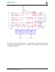
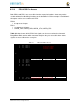
Figure 50
shows the location of the expansion connectors.
Figure 50 Expansion Connector Location
The location and spacing of the expansion headers are the same as on the original
BeagleBone.