
User Manual

element14 is a trademark of Premier Farnell plc 73
© 2014 Premier Farnell plc. All Rights Reserved
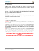
6.11 USB Host
The board is equipped with a single USB host interface accessible from a single USB Type
A female connector.
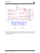
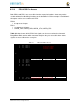
Figure 48
is the design of the USB Host circuitry.
Figure 48 USB Host Circuitry
6.11.1 Power Switch
U8
is a switch that allows the power to the connector to be turned on or off by the
processor. It also has an over current detection that can alert the processor if the current
gets too high via the
USB1_OC
signal. The power is controlled by the
USB1_DRVBUS
signal from the processor.
6.11.2 ESD Protection
U9
is the ESD protection for the signals that go to the connector.
6.11.3 Filter Options
FB7
and
FB8
were added to assist in passing the FCC emissions test. The
USB1_VBUS
signal is used by the processor to detect that the 5V is present on the connector.
FB7
is
populated and
FB8
is replaces with a .1 ohm resistor.