
User Manual


element14 is a trademark of Premier Farnell plc 70
© 2014 Premier Farnell plc. All Rights Reserved
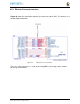
6.10.6 Audio Interface
There is an I2S audio interface between the processor and the
TDA19988
. Stereo audio
can be transported over the HDMI interface to an audio equipped display. In order to
create the required clock frequencies, and external 24.576MHz oscillator,
Y4
, is used.
From this clock, the processor generates the required clock frequencies for the
TDA19988
.
There are three signals used to pass data from the processor to the
TDA19988
. SCLK is
the serial clock. SPI1_CS0 is the data pin to the
TDA199888
. SPI1_D0 is the word sync
pin. These signals are configured as I2S interfaces.
Audio is limited to CEA supported resolutions. LCD panels only activate the audio in
CEA modes. This is a function of the specification and is not something that can be fixed
on the board via a hardware change or a software change.
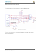
In order to create the correct clock frequencies, we had to add an external
24.576MHZ
oscillator. Unfortunately this had to be input into the processor using the pin previously
used for
GPIO3_21
. In order to keep GPIO3_21 functionality, we provided a way to
disable the oscillator if the need was there to use the pin on the expansion header.
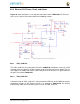
Figure
45
shows the oscillator circuitry.
Figure 45 24.576MHz Oscillator