
User Manual


element14 is a trademark of Premier Farnell plc 62
© 2014 Premier Farnell plc. All Rights Reserved
LCD panels. If you choose to override these settings, it is strongly recommended that you
gate these signals with the
SYS_RESETn
signal. This ensures that after coming out of
reset these signals are removed from the expansion pins.
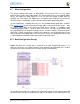
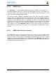
6.8 Default Boot Options
Based on the selected option found in
Figure 39
below, each of the boot sequences for
each of the two settings is shown.
Figure 39 Processor Boot Configuration
The first row in
Figure 39
is the default setting. On boot, the processor will look for the
eMMC on the MMC1 port first, followed by the microSD slot on MMC0, USB0 and UART0.
In the event there is no microSD card and the eMMC is empty, UART0 or USB0
could be used as the board source.
If you have a microSD card from which you need to boot from, hold the boot button
down. On boot, the processor will look for the SPIO0 port first, then microSD on the MMC0
port, followed by USB0 and UART0. In the event there is no microSD card and the eMMC
is empty, USB0 or UART0 could be used as the board source.
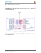
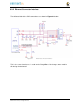
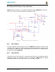
6.9 10/100 Ethernet
The e l e m e n t 1 4 BeagleBone Black is equipped with a 10/100 Ethernet interface. It
uses the same PHY as is used on the original BeagleBone. The design is described in the
following sections.