
User Manual


element14 is a trademark of Premier Farnell plc 61
© 2014 Premier Farnell plc. All Rights Reserved
6.7 Boot Configuration
The design supports two groups of boot options on the board. The user can switch
between these modes via the Boot button. The primary boot source is the onboard eMMC
device. By holding the Boot button, the user can force the board to boot from the
microSD slot. This enables the eMMC to be overwritten when needed or to just boot an
alternate image. The following sections describe how the boot configuration works.
In most applications, including those that use the provided demo distributions available
from
beagleboard.org
, the processor-external boot code is composed of two stages. After
the primary boot code in the processor ROM passes control, a secondary stage
(secondary program loader -- "SPL" or "MLO") takes over. The SPL stage initializes only
the required devices to continue the boot process, and then control is transferred to the
third stage "U-boot". Based on the settings of the boot pins, the ROM know where to go
and get the SPL and UBoot code. In the case of the element14 BeagleBone Black, that
is either eMMC or microSD based on the position of the boot switch.
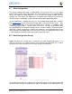
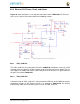
6.7.1 Boot Configuration Design
Figure 38
shows the circuitry that is involved in the boot configuration process. On
power up, these pins are read by the processor to determine the boot order. S2 is used to
change the level of one bit from HI to LO which changes the boot order.
Figure 38 Processor Boot Configuration Design
It is possible to override these setting via the expansion headers. But be careful not to add
too much load such that it could interfere with the operation of the HDMI interface or