
User Manual

element14 is a trademark of Premier Farnell plc 60
© 2014 Premier Farnell plc. All Rights Reserved
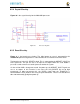
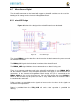
6.6 User LEDs
There are four user LEDs on the element14 BeagleBone Black. These are connected
to GPIO pins on the processor.
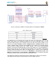
Figure 37
shows the interfaces for the user LEDs.
Figure 37 User LEDs
Resistors R71-R74 was changed to 4.75K on the revision A5B board.
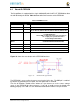
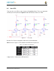
Table 7 shows the signals used to control the four LEDs from the processor.
Table 7 User LED Control Signals/Pins
A logic level of “1” will cause the LEDs to turn on.