
User Manual

element14 is a trademark of Premier Farnell plc 59
© 2014 Premier Farnell plc. All Rights Reserved
6.5 Micro Secure Digital
The microSD connector on the board will support a microSD card that can be used for
booting or file storage on the element14 BeagleBone Black.
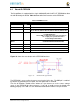
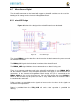
6.5.1 microSD Design
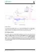
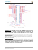
Figure 36
below is the design of the microSD interface on the board.
Figure 36 microSD Design
The signals
MMC0-3
are the data lines for the transfer of data between the processor and
the microSD connector.
The
MMC0_CLK
signal clocks the data in and out of the microSD card.
The
MMCO_CMD
signal indicates that a command versus data is being sent.
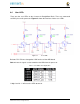
There is no separate card detect pin in the microSD specification. It uses
MMCO_DAT3
for that function. However, most microSD connectors still supply a CD function on the
connectors. In the element14 BeagleBone Black design, this pin is connected to the
MMC0_SDCD
pin for use by the processor. You can also change the pin to
GPIO0_6
,
which is able to wake up the processor from a sleep mode when an microSD card is
inserted into the connector.
Pullup resistors are provided on the signals to increase the rise times of the signals to
overcome PCB capacitance.
Power is provided from the
VDD_3V3B
rail and a 10uf capacitor is provided for
filtering.