
User Manual

element14 is a trademark of Premier Farnell plc 56
© 2014 Premier Farnell plc. All Rights Reserved
6.3 4GB eMMC Memory
The eMMC is a communication and mass data storage device that includes a Multi-
MediaCard (MMC) interface, a NAND Flash component, and a controller on an
advanced 11-signal bus, which is compliant with the MMC system specification. The
nonvolatile eMMC draws no power to maintain stored data, delivers high performance
across a wide range of operating temperatures, and resists shock and vibration disruption.
One of the issues faced with SD cards is that across the different brands and even within
the same brand, performance can vary. Cards use different controllers and different
memories, all of which can have bad locations that the controller handles. But the
controllers may be optimized for reads or writes. You never know what you will be getting.
This can lead to varying rates of performance. The eMMC card is a known controller and
when coupled with the 8bit mode, 8 bits of data instead of 4, you get double the
performance which should result in quicker boot times.
The following sections describe the design and device that is used on the board to
implement this interface.
6.3.1 eMMC Device
The device used is one of two different devices:
•
Micron MTFC4GLDEA 0M WT
•
Kingston KE4CN2H5A-A58
The package is a 153 ball WFBGA device on both devices.
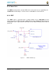
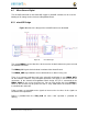
6.3.2 eMMC Circuit Design
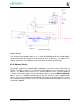
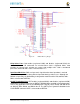
Figure 34
is the design of the eMMC circuitry. The eMMC device is connected to the
MMC1 port on the processor. MMC0 is still used for the microSD card as is currently
done on the original BeagleBone. The size of the eMMC supplied is now 4GB.
The device runs at 3.3V both internally and the external I/O rails. The VCCI is an
internal voltage rail to the device. The manufacturer recommends that a 1uf capacitor be
attached to this rail, but a 2.2uF was chosen to provide a little margin.
Pullup resistors are used to increase the rise time on the signals to compensate for any
capacitance on the board.