
User Manual

element14 is a trademark of Premier Farnell plc 51
© 2014 Premier Farnell plc. All Rights Reserved
6.2.4 Crystal Circuitry
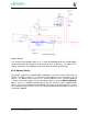
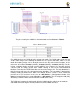
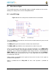
Figure 30
is the crystal circuitry for the AM3358B processor.
Figure 30 Processor Crystals
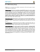
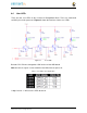
6.2.5 Reset Circuitry
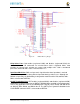
Figure 31
is the board reset circuitry. The initial power on reset is generated by the
TPS65217C
power management IC. It also handles the reset for the Real Time Clock.
The board reset is the SYS_RESETn signal. This is connected to the NRESET_INOUT pin
of the processor. This pin can act as an input or an output. When the reset button is
pressed, it sends a warm reset to the processor and to the system.
On the revision A5D a change was made. On power up, the NRESET_INOUT signal can
act as an output. In this instance it can cause the SYS_RESETn line to go high
prematurely. In order to prevent this, the PORZn signal from the TPS65217C is
connected to the SYS_RESETn line using an open drain buffer. These insure that the line
does not momentarily go high on power up.