
User Manual

element14 is a trademark of Premier Farnell plc 48
© 2014 Premier Farnell plc. All Rights Reserved
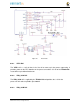
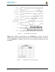
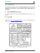
6.1.12 Processor Control Interface
Figure 28
above shows two interfaces between the processor and the
TPS65217C
used
for control after the power up sequence has completed.
The first is the
I2C0
bus. This allows the processor to turn on and off rails and to set the
voltage levels of each regulator to supports such things as voltage scaling.
The second is the interrupt signal. This allows the T
PS65217C
to alert the processor
when there is an event, such as when the optional power button is pressed. The interrupt
is an open drain output which makes it easy to interface to 3.3V of the processor.
6.1.13 Low Power Mode Support
This section covers three general power down modes that are available. These modes are
only described from a Hardware perspective as it relates to the HW design.
6.1.13.1 RTC Only
In this mode all rails are turned off except the
VDD_RTC
. The processor will need to
turn off all the rails to enter this mode. The
VDD_RTC
staying on will keep the RTC active
and provide for the wakeup interfaces to be active to respond to a wake up event.
6.1.13.2 RTC Plus DDR
In this mode all rails are turned off except the
VDD_RTC
and the
VDDS_DDR
, which
powers the DDR3L memory. The processor will need to turn off all the rails to enter this
mode. The
VDD_RTC
staying on will keep the RTC active and provide for the wakeup
interfaces to be active to respond to a wake up event.
The
VDDS_DDR
rail to the DDR3L is provided by the 1.5V rail of the
TPS65217C
and
with
VDDS_DDR
active, the DDR3L can be placed in a self refresh mode by the
processor prior to power down which allows the memory data to be saved.
Currently, this feature is not included in the standard software release. The plan is to
include it in future releases.