
User Manual

element14 is a trademark of Premier Farnell plc 47
© 2014 Premier Farnell plc. All Rights Reserved
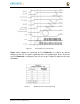
6.1.10 Power LED
The power LED is a blue LED that will turn on once the
TPS65217C
has finished the
power up procedure. If you ever see the LED flash once, that means that the
TPS65217C
started the process and encountered an issue that caused it to shut down. The
connection of the LED is shown in
Figure 25
.
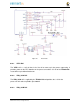
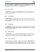
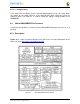
6.1.11 TPS65217C Power Up Process
Figure 28
shows the interface between the
TPS65217C
and the processor. It is a cut from
the PDF form of the schematic and reflects what is on the schematic.
Figure 28 Power Processor Interfaces
When voltage is applied, DC or USB, the
TPS65217C
connects the power to the SYS
output pin which drives the switchers and LDOs in the
TPS65217C
.
At power up all switchers and LDOs are off except for the
VRTC LDO
(1.8V), which
provides power to the VRTC rail and controls the
RTC_PORZn
input pin to the processor,
which starts the power up process of the processor. Once the RTC rail powers up, the
RTC_PORZn
pin, driven by the
LDO_PGOOD
signal from the
TPS65217C
, of the
processor is released.
Once the
RTC_PORZn
reset is released, the processor starts the initialization process.
After the RTC stabilizes, the processor launches the rest of the power up process by
activating the
PMIC_POWER_EN
signal that is connected to the
TPS65217C
which starts
the
TPS65217C
power up process.
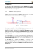
The
LDO_PGOOD
signal is provided by the
TPS65217C
to the processor. As this
signal is 1.8V from the
TPS65217C
by virtue of the
TPS65217C
VIO rail being set to
1.8V, and the
RTC_PORZ
signal on the processor is 3.3V, a voltage level shifter,
U4
, is
used. Once the LDOs and switchers are up on the
TPS65217C
, this signal goes active
releasing the processor. The LDOs on the
TPS65217C
are used to power the VRTC rail
on the processor.