
User Manual

element14 is a trademark of Premier Farnell plc 45
© 2014 Premier Farnell plc. All Rights Reserved
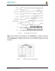
The current supplied by the
VDD_3V3A
rail is not sufficient to power all of the 3.3V
rails on the board. So a second LDO is supplied, U4, a
TL5209A
, which sources the
VDD_3V3B
rail. It is powered up just after the
VDD_3V3A
rail.
6.1.9.4 VDD_1V8 Rail
The
VDD_1V8
rail can deliver up to 400mA and provides the power required for the
1.8V rails on the processor and the HDMI framer. This rail is not accessible for use
anywhere else on the board.
6.1.9.5 VDD_CORE Rail
The
VDD_CORE
rail can deliver up to 1.2A at 1.1V. This rail is not accessible for use
anywhere else on the board and connects only to the processor. This rail is fixed at 1.1V
and is should not be adjusted by SW using the PMIC. If you do, then the processor will
no longer process..
6.1.9.6 VDD_MPU Rail
The
VDD_MPU
rail can deliver up to 1.2A. This rail is not accessible for use anywhere
else on the board and connects only to the processor. This rail defaults to 1.1V and can be
scaled up to allow for higher frequency operation. Changing of the voltage is set via the
I2C interface from the processor.
6.1.9.7 VDDS_DDR Rail
The
VDDS_DDR
rail defaults to
1.5V
to support the DDR3L rails and can deliver up to
1.2A. It is possible to adjust this voltage rail down to
1.35V
for lower power operation of
the DDR3L device. Only DDR3L devices can support this voltage setting of 1.35V.
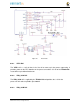
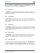
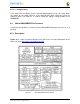
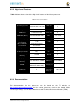
6.1.9.8 Power Sequencing
The power up process is consists of several stages and events.
Figure 26
describes
the events that make up the power up process for the processer from the PMIC. This
diagram is used elsewhere to convey additional information. I saw no need to bust it
up into smaller diagrams. It is from the processor datsheet supplied by Texas Instruments.