
User Manual

element14 is a trademark of Premier Farnell plc 42
© 2014 Premier Farnell plc. All Rights Reserved
6.1.7 Power Consumption
The power consumption of the board varies based on power scenarios and the board boot
processes. Measurements were taken with the board in the following configuration:
•
DC powered and USB powered
•
HDMI monitor connected
•
USB HUB
•
4GB Thumbdrive
•
Ethernet connected @ 100M
•
Serial debug cable connected
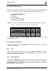
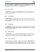
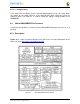
Table 3
is an analysis of the power consumption of the board in these various scenarios.
Table 3 element14
BeagleBone Black Power Consumption (mA@5V)
M
ODE
USB
DC
D
C
+USB
R
e
s
e
t
T
B
D
T
B
D
T
B
D
I
d
l
in
g @
UBoot
210
210
210
K
e
r
n
e
l
B
ooting (
Pe
a
k
)
460
460
460
Kernel Idling
350 350 350
K
e
r
n
e
l I
d
l
in
g
Dis
p
lay
B
la
n
k
280 280 280
Loa
d
i
n
g a W
eb
p
age
430 430 430
The current will fluctuate as various activates occur, such as the LEDs on and
microSD/eMMC accesses.
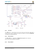
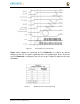
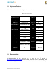
6.1.8 Processor Interfaces
The processor interacts with the
TPS65217C
via several different signals. Each of these
signals is described below.
6.1.8.1 I2C0
I2C0 is the control interface between the processor and the
TPS65217C
. It allows the
processor to control the registers inside the
TPS65217C
for such things as voltage
scaling and switching of the input rails.
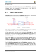
6.1.8.2 PMC_POWR_EN
On power up the
VDD_RTC
rail activates first. After the RTC circuitry in the processor has
activated it instructs the
TPS65217C
to initiate a full power up cycle by activating the
PMIC_POWR_EN
signal by taking it HI. When powering down, the processor can take this
pin low to start the power down process.