
User Manual

element14 is a trademark of Premier Farnell plc 37
© 2014 Premier Farnell plc. All Rights Reserved
can be forced into fixed frequency PWM using the I
2
C interface. The step-down converters
allow the use of small inductors and capacitors to achieve a small footprint solution
size.
LDO1 and LDO2 are intended to support system standby mode. In normal operation,
they can support up to 100mA each. LDO3 and LDO4 can support up to 285mA each.
By default only LDO1 is always ON but any rail can be configured to remain up in
SLEEP state. In particular the DCDC converters can remain up in a low-power PFM
mode to support processor suspend mode. The
TPS65217C
offers flexible power-up and
power-down sequencing and several house-keeping functions such as power-good output,
pushbutton monitor, hardware reset function and temperature sensor to protect the
battery.
For more information on the
TPS65217C
, refer to http://www.ti.com/product/tps65217C.
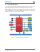
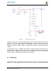
Figure 22
is the high level block diagram of the
TPS65217C
.