
User Manual

element14 is a trademark of Premier Farnell plc 34
© 2014 Premier Farnell plc. All Rights Reserved
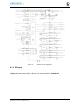
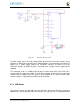
5.12 CTI JTAG Header
A place for an optional 20 pin CTI JTAG header is provided on the board to facilitate the
SW development and debugging of the board by using various JTAG emulators. This
header is not supplied standard on the board. To use this, a connector will need to be
soldered onto the board.
If you need the JTAG connector you can solder it on yourself. No other components are
needed. The connector is made by Samtec and the part number is FTR-110-03-G-D-06.
You can purchase it from www.newark.com.
5.13 HDMI Interface
A single HDMI interface is connected to the 16 bit LCD interface on the processor. The
16b interface was used to preserve as many expansion pins as possible to allow for use
by the user. The NXP TDA19988BHN is used to convert the LCD interface to HDMI and
convert the audio as well. The signals are still connected to the expansion headers to
enable the use of LCD expansion boards or access to other functions on the board as
needed.
The HDMI device does not support HDCP copy protection. Support is provided via
EDID to allow the SW to identify the compatible resolutions. Currently the following
resolutions are supported via the software:
•
1280 x 1024
•
1440 x 900
•
1024 x 768
•
1280 x 720
5.14 Cape Board Support
The element14 BeagleBone Black has the ability to accept up to four expansion boards or
capes that can be stacked onto the expansion headers. The word cape comes from the
shape of the board as it is fitted around the Ethernet connector on the main board. This
notch acts as a key to ensure proper orientation of the cape.
The majority of capes designed for the original BeagleBone will work on the element14
BeagleBone Black. The two main expansion headers will be populated on the board.
There are a few exceptions where certain capabilities may not be present or are limited to
the element14 BeagleBone Black. These include:
•
GPMC bus may NOT be available due to the use of those signals by the eMMC. If
the eMMC is used for booting only and the file system is on the microSD card, then
these signals could be used.
•
Another option is to use the microSD or serial boot modes and not use the eMMC.
•
The power expansion header is not on the elem ent14 BeagleBone Black so
those functions are not supported.
For more information on cape support refer to Section 9.0.