
User Manual

element14 is a trademark of Premier Farnell plc 27
© 2014 Premier Farnell plc. All Rights Reserved
4.3 Board Component Locations
This section describes the key components on the board. It provides information on their
location and function. Familiarize yourself with the various components on the board.
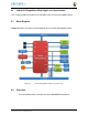
4.3.1 Connectors, LEDs, and Switches
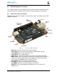
Figure 17
below shows the locations of the connectors, LEDs, and switches on the PCB
layout of the board.
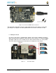
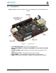
Figure 17
Connectors, LEDs and Switches
•
DC Power
is the main DC input that accepts 5V power.
•
Power Button
alerts the processor to initiate the power down sequence.
•
10/100 Ethernet
is the connection to the LAN.
•
Serial Debug
is the serial debug port.
•
USB Client
is a miniUSB connection to a PC that can also power the board.
•
BOOT switch
can be used to force a boot from the microSD card if the power is
cycled on the board, removing power and reapplying the power to the board..
•
There are four blue
LED
S that can be used by the user.
•
Reset Button
allows the user to reset the processor.
•
microSD
slot is where a microSD card can be installed.
•
microHDMI
connector is where the display is connected to.
•
USB Host
can be connected different USB interfaces such as Wi-Fi, BT,
Keyboard, etc.