
User Manual


element14 is a trademark of Premier Farnell plc 108
© 2014 Premier Farnell plc. All Rights Reserved
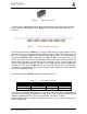
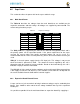
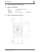
Figure 70 Cape Board Dimensions
A slot is provided for the Ethernet connector to stick up higher than the cape when
mounted. This also acts as a key function to ensure that the cape is oriented correctly.
Space is also provided to allow access to the user LEDs and reset button on the main
board.
Some people have inquired as to the difference in the radius of the corners of the
element14 BeagleBone Black and why they are different. This is a result of having the
BeagleBone fit into the Altoids style tin.
It is not required that the cape be exactly like the element14 BeagleBone Black board in
this respect.
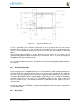
8.7.2 Extended Cape Size
Capes larger than the standard board size are also allowed. A good example would be an
LCD panel. There is no practical limit to the sizes of these types of boards. The notch for
the key is also not required, but it is up to the supplier of these boards to ensure that the
element14 BeagleBone Black is not plugged in incorrectly in such a manner that damage
would be cause to the e l e m e n t 1 4 BeagleBone Black or any other capes that
may be installed. Any such damage will be the responsibility of the supplier of such a
cape to repair.
As with all capes, the EEPROM is required and compliance with the power requirements
must be adhered to.
8.7.3 Enclosures