
User Manual


element14 is a trademark of Premier Farnell plc 107
© 2014 Premier Farnell plc. All Rights Reserved
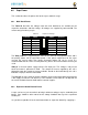
5V signal into the
VDD_5V
rail, the main board can be supplied. This voltage must not
exceed 5V. You should not supply any voltage into any other pin of the expansion
connectors. Based on the board design, this rail is limited to 1A per pin to the
element14 BeagleBone Black.
There are several precautions that need to me taken when working with the expansion headers to
prevent damage to the board.
1) Do not apply any voltages to any I/O pins when the board is not powered on.
2) Do not drive any external signals into the I/O pins until after the VDD_3V3B rail is up.
3) Do not apply any voltages that are generated from external sources.
4) If voltages are generated from the VDD_5V signal, those supplies must not become active until
after the VDD_3V3B rail is up.
5) If you are applying signals from other boards into the expansion headers, make sure you power
the board up after you power up the element14 BeagleBone Black or make the connections after
power is applied on both boards.
Powering the processor via its I/O pins can cause damage to the processor.
8.7 Mechanical
This section provides the guidelines for the creation of expansion boards from a
mechanical standpoint. Defined is a standard board size that is the same profile as the
element14 BeagleBone Black. It is expected that the majority of expansion boards created
will be of standard size. It is possible to create boards of other sizes and in some cases
this is required, as in the case of an LCD larger than the element14 BeagleBone Black
board.
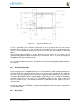
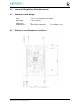
8.7.1 Standard Cape Size
Figure 70
is the outline of the standard cape. The dimensions are in inches.