
User Manual


element14 is a trademark of Premier Farnell plc 104
© 2014 Premier Farnell plc. All Rights Reserved
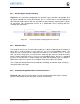
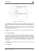
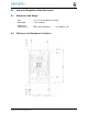
Figure 69 Connector Pin Insertion Depth
To calculate the amount of the pin that extends past the Point of Contact, use the following
formula:
Overhang=Total Pin Length- PCB thickness (.062) - contact point (.079)
The longer the pin extends past the contact point, the more force it will take to insert and
remove the board. Removal is a greater issue than the insertion.
8.5 Signal Usage
Based on the pin muxing capabilities of the processor, each expansion pin can be
configured for different functions. When in the stacking mode, it will be up to the user to
ensure that any conflicts are resolved between multiple stacked cards. When stacked, the
first card detected will be used to set the pin muxing of each pin. This will prevent other
modes from being supported on stacked cards and may result in them being inoperative.
In
Section 7.1
of this document, the functions of the pins are defined as well as the pin
muxing options. Refer to this section for more information on what each pin is. To simplify
things, if you use the default name as the function for each pin and use those
functions, it will simplify board design and reduce conflicts with other boards.
Interoperability is up to the board suppliers and the user. This specification does not
specify a fixed function on any pin and any pin can be used to the full extent of the
functionality of that pin as enabled by the processor.