
User Manual

element14 is a trademark of Premier Farnell plc 103
© 2014 Premier Farnell plc. All Rights Reserved
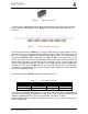
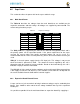
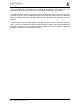
8.4.3 Stacked Capes w/Signal Stealing
Figure 68
is the connector configuration for stackable capes that does not provide all of
the signals upwards for use by other boards. This is useful if there is an expectation that
other boards could interfere with the operation of your board by exposing those signals
for expansion. This configuration consists of a combination of the stacking and non-
stacking style connectors.
Figure 68 Stacked w/Signal Stealing Expansion Connector
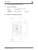
8.4.4 Retention Force
The length of the pins on the expansion header has a direct relationship to the amount of
force that is used to remove a cape from the e l e m e n t 1 4 BeagleBone Black. The
longer the pins extend into the connector the harder it is to remove. There is no rule
that says that if longer pins are used, that the connector pins have to extend all the way
into the mating connector on the e l e m e n t 1 4 BeagleBone Black, but this is controlled
by the user and therefore is hard to control. We have also found that if you use gold pins,
While more expensive, it makes for a smoother finish which reduces the friction.
This section will attempt to describe the tradeoffs and things to consider when selecting a
connector and its pin length.
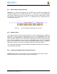
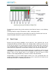
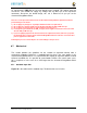
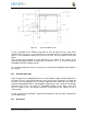
8.4.5 element14 BeagleBone Black Female Connectors
Figure 69
shows the key measurements used in calculating how much the pin extends
past the contact point on the connector, what we call overhang.