
User Manual


element14 is a trademark of Premier Farnell plc 102
© 2014 Premier Farnell plc. All Rights Reserved
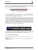
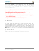
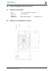
Figure 66 Expansion Connector
The connector is mounted on the top side of the board with longer tails to allow insertion
into the element14 BeagleBone Black.
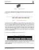
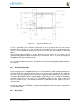
Figure 67
is the connector configuration for the
connector.
Figure 67 Stacked Cape Expansion Connector
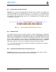
For convenience listed in
Table 19
are some possible choices for part numbers on this
connector. They have varying pin lengths and some may be more suitable than others for
your use. It should be noted, that the longer the pin and the further it is inserted into the
element14 BeagleBone Black connector, the harder it will be to remove due to the
tension on 92 pins. This can be minimized by using shorter pins. There are most likely
other suppliers out there that will work for this connector as well. If anyone finds other
suppliers of compatible connectors that work, let us know and they will be added to this
document. The first item in
Table 19
is on the edge and may not be the best solution.
Overhang is the amount of the pin that goes past the contact point of the connector on the
element14 BeagleBone Black.
The third part listed in
Table 20
will have insertion force issues.
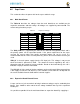
Table 19
Stacked Cape Connectors
S
UPPLIER
PART
N
UM
B
ER
TA
I
L LEN
G
T
H
(
i
n
)
O
V
ER
H
A
N
G
(
m
m
)
Major
L
e
a
g
u
e
SSHQ-123-D-06-G-
LF
.190
0.049
Major League
SSHQ-123-D-08-G-
LF
.390 0.249
Major League
SSHQ-123-D-10-G-
LF
.560 0.419
There are also different plating options on each of the connectors above. Gold plating on
the contacts is the minimum requirement. If you choose to use a different part number for
plating or availability purposes, make sure you do not select the “LT” option.
Other possible sources are Sullins and Samtec but make sure you select one that has the
correct mating depth.