
User Manual


element14 is a trademark of Premier Farnell plc 101
© 2014 Premier Farnell plc. All Rights Reserved
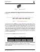
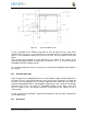
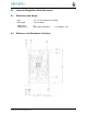
The connector is typically mounted on the bottom side of the board as shown in
Figure
65
. These are very common connectors and should be easily located. You can also
use two single row 23 pin headers for each of the dual row headers.
Figure 65 Single Cape Expansion Connector
It is allowed to only populate the pins you need. As this is a non-stacking configuration,
there is no need for all headers to be populated. This can also reduce the overall cost
of the cape. This decision is up to the cape designer.
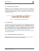
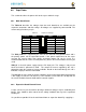
For convenience listed in
Table 18
are some possible choices for part numbers on this
connector. They have varying pin lengths and some may be more suitable than others
for your use. It should be noted, that the longer the pin and the further it is inserted into
the element14 BeagleBone Black connector, the harder it will be to remove due to the
tension on 92 pins. This can be minimized by using shorter pins or removing those
pins that are not used by your particular design. The first item in
Table 17
is on the
edge and may not be the best solution. Overhang is the amount of the pin that goes past
the contact point of the connector on the BeagleBone Black
.
Table 18
Single Cape Connectors
S
UPPLIER
PART
N
UM
B
ER
TA
I
L LEN
G
T
H
(
i
n
)
O
V
ER
H
A
N
G
(i
n
)
Major League
TSHC-123-D-03-145-G-LF
.145 .004
Major League
TSHC-123-D-03-240-G-LF
.240 .099
Major League
T
SH
C
-
12
3
-
D
-
0
3
-
255
-
G
-
LF
.255 .114
The G in the part number is a plating option. Other options may be used as well as long
as the contact area is gold. Other possible sources are Sullins and Samtec for these
connectors. You will need to ensure the depth into the connector is sufficient
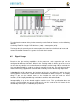
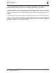
8.4.2 Main Expansion Headers-Stacking
For stacking configuration, the two 46 pin expansion headers use the same
connectors.
Figure 66
is a picture of the connector. These are dual row 23 position 2.54mm x
2.54mm connectors.