
User Manual


element14 is a trademark of Premier Farnell plc 100
© 2014 Premier Farnell plc. All Rights Reserved
If you plan to use any of these signals, then on power up, these pins should not be driven.
If you do, it can affect the boot mode of the processor and could keep the processor from
booting or working correctly.
If you are designing a cape that is intended to be used as a boot source, such as a NAND
board, then you should drive the pins to reconfigure the boot mode, but only at reset.
After the reset phase, the signals should not be driven to allow them to be used for the
other functions found on those pins. You will need to override the resistor values in order
to change the settings. The DC pull-up requirement should be based on the AM3358 Vih
min voltage of 2 volts and AM3358 maximum input leakage current of 18uA. Also take into
account any other current leakage paths on these signals which could be caused by your
specific cape design.
The DC pull-down requirement should be based on the AM3358 Vil max voltage of 0.8
volts and AM3358 maximum input leakage current of 18uA plus any other current
leakage paths on these signals.
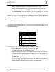
8.4 Expansion Connectors
A combination of male and female headers is used for access to the expansion headers
on the main board. There are three possible mounting configurations for the expansion
headers:
Single-no board stacking but can be used on the top of the stack.
Stacking-up to four boards can be stacked on top of each other.
Stacking with signal stealing-up to three boards can be stacked on top of each
other, but certain boards will not pass on the signals they are using to prevent signal
loading or use by other cards in the stack.
The following sections describe how the connectors are to be implemented and used for
each of the different configurations.
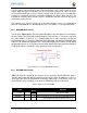
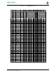
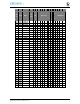
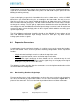
8.4.1 Non-Stacking Headers-Single Cape
For non-stacking capes single configurations or where the cape can be the last board on
the stack, the two 46 pin expansion headers use the same connectors.
Figure 64
is a
picture of the connector. These are dual row 23 position 2.54mm x 2.54mm connectors.
Figure 64 Single Expansion Connector