
Data Sheet


AM3359, AM3358, AM3357
AM3356, AM3354, AM3352
SPRS717F –OCTOBER 2011–REVISED APRIL 2013
www.ti.com
5.6 External Memory Interfaces
The device includes the following external memory interfaces:
• General-purpose memory controller (GPMC)
• mDDR(LPDDR), DDR2, DDR3, DDR3L Memory Interface (EMIF)
5.6.1 General-Purpose Memory Controller (GPMC)
NOTE
For more information, see the Memory Subsystem and General-Purpose Memory Controller
section of the AM335x ARM Cortex-A8 Microprocessors (MPUs) Technical Reference
Manual (literature number SPRUH73).
The GPMC is the unified memory controller used to interface external memory devices such as:
• Asynchronous SRAM-like memories and ASIC devices
• Asynchronous page mode and synchronous burst NOR flash
• NAND flash
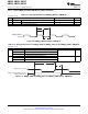
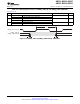
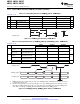
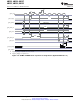
5.6.1.1 GPMC and NOR Flash—Synchronous Mode
Table 5-21 and Table 5-22 assume testing over the recommended operating conditions and electrical
characteristic conditions below (see Figure 5-17 through Figure 5-21).
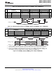
Table 5-20. GPMC and NOR Flash Timing Conditions—Synchronous Mode
TIMING CONDITION PARAMETER MIN TYP MAX UNIT
Input Conditions
t
R
Input signal rise time 1 5 ns
t
F
Input signal fall time 1 5 ns
Output Condition
C
LOAD
Output load capacitance 3 30 pF
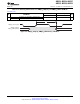
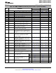
Table 5-21. GPMC and NOR Flash Timing Requirements—Synchronous Mode
OPP100 OPP50
NO. UNIT
MIN MAX MIN MAX
F12 t
su(dV-clkH)
Setup time, input data gpmc_ad[15:0] valid before output clock 3.2 13.2 ns
gpmc_clk high
F13 t
h(clkH-dV)
Hold time, input data gpmc_ad[15:0] valid after output clock 4.74 2.75 ns
gpmc_clk high
F21 t
su(waitV-clkH)
Setup time, input wait gpmc_wait[x]
(1)
valid before output clock 3.2 13.2 ns
gpmc_clk high
F22 t
h(clkH-waitV)
Hold time, input wait gpmc_wait[x]
(1)
valid after output clock 4.74 2.75 ns
gpmc_clk high
(1) In gpmc_wait[x], x is equal to 0 or 1.
126 Peripheral Information and Timings Copyright © 2011–2013, Texas Instruments Incorporated
Submit Documentation Feedback
Product Folder Links: AM3359 AM3358 AM3357 AM3356 AM3354 AM3352