
Install Instructions

TYPE "F" :
1.) Locate the heater at or near fl oor level, and plan for
water and electrical services feed through the bottom
of the enclosure. If over rough fl ooring, be sure to
allow clearance above the fi nish that will not interfere
with removal of the front panel. The back panel (Item
2F) should be screwed or nailed securely to the wall.
2.) Remove the front panel (Item 1F) by removing the two
screws at the bottom. Then pull the bottom away from
the enclosure and lift the top from its hooked position.
To replace the panel, press down fi rmly to engage it in
the top channel and lock the two sides over the front
edge of the enclosure at the clamps.
3.) Mount the Kickspace Unit (Item 3) to the back recessed
panel, remove the electrical control box cover from Kick-
space unit. Secure the Kickspace unit in place using
items 5 & 6 as shown in Figure F. Do not over tighten.
4.) Soldering may be done to the kickspace unit (Item 3)
with care within Type "F" enclosure, or the element
may easily be removed, if so desired.
CAT-55525A
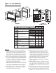
2F
6
5
7
3
4F
8
9
1F
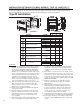
17 27/32 (453) F42
21 27/32 (555) F84
21 27/32 (555) F120
23 29/32
(607)
4 3/8
(111)
18" (460) F42
22" (561) F84
22" (561) F120
24"
(610)
3.
Type "F" Installation
5.) After the piping connections are made, replace the
heating element in the bottom cover in the proper
postition. Place the neoprene side pad in position
and replace the top cover using the 4 screws. Tighten
enough to keep the element in place between the cov-
ers. DO NOT OVER-TIGHTEN! Removal and replace-
ment will be simpler if done in a horizontal position
before the enclosure is secured to the wall.
6.) Electrical connections for the wall units are to be
made as indicated in Type "K" Kickspace Installation
Manual on page 3.
7.) Make fi nal piping and electrical connections (see pag-
es 5 & 6 in Type K Installation Manual) to the system
in the cabinet. Turn on the system, purge of air, check
blower operation, and check for any possible leaks in
the piping.
8.) Replace front panel (Item 1F), place washers (Item 8)
in required positions, screw through holes and tighten.
9.) Place snap-cap
®
(Item 9) over washer at angle. Push
snap-cap
®
(Item 9) DOWN fi rmly until it engages with
a snap.
FIGURE F
Model
Description Part No. 42 84 120
Figure F Parts List
1F Front Panel Assembly
BMFR02165-001 x
BMFR02165-002 x x
2F Back Panel Assembly
BMFR02161-001 x
BMFR02161-002 x x
3 Kickspace Unit (sold separately)
K42 x
K84 x
K120 x
4F Front Panel Mounting Screws J21-00282-003 x x x
5 Lockwashers J24-00322-001 x x x
6 Flanged Nuts J23-00324-001 x x x
7 Kickspace Electrical Box Cover ref item #3 x x x
8/9 Snap Cap / Washers J06-04481 x x x
Figure F
Complete Surface Mount Wall Kit Type "F"
(less heater)
F42 x
F84 x
F120 x
FIGURE G
(Model 42 Shown)