
Install Instructions
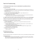

Beacon Morris Twin-Flo III Heaters should be connected only to circulating hot water systems where at least 1
gpm water ow is expected. They are essentially small unit heaters, and will work on one or two pipe systems, or
in a series loop where pressure and temperature drop can be tolerated (see capacity charts and piping diagrams).
These units are not designed for use with steam systems. See bottom paragraph on page 7. These units are not
recommended to be used with a gravity ow system. Series loop systems do not require scoop or venturi tees.
4.
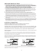
Piping Charts
SYSTEM CONSIDERATIONS
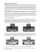
NOTE: In an up feed system, unit is located above hot water supply line. In a down feed
system, unit is located below hot water supply line.
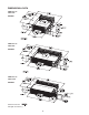
For One Pipe System Down Feed, two directional ow tees should be used. They should be spaced 12
to 18" apart. To better understand directional ow tee installation, refer to page 5.
If directional ow tee's are not available, an adjustable screw operated ow control or circuit setter
can be placed between the two standard tee's in a one pipe system.
For consistent response of the reverse acting thermostat, and effective outlet air temperature, the
average water temperature should not be below 120°F (49°C). Blower motor shuts off at 105°F (41°C)
and will not operate until water temperature reaches 120°F (49°C).
If utilizing water temperature below 120°F (49°C), the blower will not operate with the self contained
aquastat. An optional low temperature aquastat, 110° to 95°F (43° to 35°C) is available.
Installation should be done with as few ttings as possible. Multiple ttings may cause too much resistance.
FIGURE 4 FIGURE 5
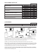
K-42
K-84
K-120
1 GALLON
2 GALLONS
3 GALLONS
.50
.50
.74
.17'
.8'
1.2'
53
103
127
30.7
30.7
66.8
.22'
.95'
1.5'
AMPUNIT K42CFM (HIGH SPEED)
MOTOR INFORMATION FRICTION LOSS (HEAD)
3200
3200
3200
.43'
1.45'
2.97'
.034
.034
.068
115
115
115
WATT K84VOLTAGERPM K120HP
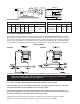
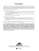
WIRING DIAGRAM 3
TWIN-FLO
ROOM T'STAT
12
115V LINE
CIRCULATOR
ZONE VALVE
W/AUX. SW.
TRANS
LOW VOLT
115/24V
MIN
MAX
T-STAT
(NEUTRAL)L2
115/1/60
LINE IN
L1
BLUE
(HOT)
SPDT
2
1
3
BLOWER
WHT
MOTOR
BLK
RED
CAT-68254-A
BLUE
OFF
WIRING DIAGRAM C