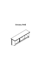
Congratulations! You have purchased a stylish piece. We strives to provide fine furniture products, built with quality materials and hand finished details. Please carefully follow the assembly instructions to ensure your furniture is assembled correctly to provide long lasting enjoyment. Should you experience any missing or damaged parts, do not return to the store. Care: Use a soft clean cloth that will not scratch the surface when dusting. Use of furniture polish is not necessary.
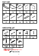
PART LIST A Left Side Panel Right Side Panel Left Partition Right Partition Top Panel Panel 1PC 1PC 1PC 1PC 1PC Back Panel Upper Back Rail | Lower Back Panel Bottom Panel Support Plate 1PC 1PC 1PC 1PC 1PC 28*30 Wood Dowel Cam Bolt Cam Lock Hook Round Head Screw PCS 15 PCS 15 PCS PCS 6 PCS | Short Flat long round Wall Anchor Head Screw head screw 4 PCS PCS 4 PCS ADDITIONAL TOOLS (Not Provided) Doter: 1t '8 ol recommended o uas power ks during assembly.
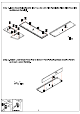
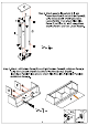
Step 1. Insert Cam Bolts (Part#2) into Top (A), Left Side Panel (B), Right Side Panel (C) and Bottom Panel (1). Step 2. Attach Lower Back Panel (H) to Bottom Panel (1) using Wood dowels (Part#1) and Cam Locks (Part#3).
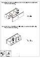
Step 3. Attach assembled parts (H & 1) and Upper Back Rail (G) to Left Side Panel (B) using Wood dowels (Part#1) and Cam Locks (Part#3). Then attach Right Side Panel (C) to Parts using Wood dowels (Part#1) and Cam Locks (Part#3). 1 ) 38x5 Step 4. Attach Left Partition Panel (D) and Right Partition Panel (E) to Bottom Panel (I} using Wood Dowels (Part#1) and Short Flat Head Screws (Part#5). Insert Back Panel (F) into grooves of Left Side Panel (B), Right Side Panel (C) and Bottom Panel (1).
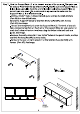
Step 5. Attach Top (A) to assembled parts )using Wood dowels (Part#1) and Cam Locks (Part#3). BX6 Step 6. Screw Hooks (Part#4) into pre drilled holes on Lower Back Panel (H) using Round Head Screws (Part#5).
Step 7. Hold the Support Plate (J) in the desired location of the wall unit. This plate will be about 2" lower than the top of the wall unit. Making sure the Support Plate (J) is level, use a pencil to mark the anchor locations using the Support Plate (J) screw holes as a guide. We recommend using a leveler to make sure the Support Plate (J) is oriented correctly. Drill two 11/32” holes in these marked spots and tap the Wall Anchors (Part #8) into the drilled holes.