
User`s manual
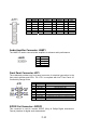


Audio Amplifier Connector: JAMP1
The JAMP1 is used to connect audio amplifiers to enhance audio performance.
Front Panel Connector: JFP1
The mainboard provides one front panel connector for electrical connection to the
front panel switches and LEDs. The JFP1 is compliant with Intel
®
Front Panel I/O
Connectivity Design Guide.
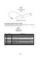
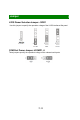
S/PDIF-Out Connector: JSPDO1
This connector is used to connect S/PDIF (Sony & Philips Digital Interconnect
Format) interface for digital audio transmission.
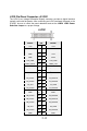
PIN SIGNAL PIN SIGNAL PIN SIGNAL PIN SIGNAL
1 RSTB# 2 AFD# 15 PRND6 16 GND
3 PRND0 4 ERR# 17 PRND7 18 GND
5 PRND1 6 PINIT# 19 ACK# 20 GND
7 PRND2 8 LPT_SLIN# 21 BUSY 22 GND
9 PRND3 10 GND 23 PE 24 GND
11 PRND4 12 GND 25 SLCT 26 KEY
13 PRND5 14 GND
PIN SIGNAL
1 AMP_L-
2 AMP_L+
3 AMP_R-
4 AMP_R+
PIN SIGNAL DESCRIPTION
1 HD_LED + Hard disk LED pull-up
2 FPPWR/SLP MSG LED pull-up
3 HD_LED - Hard disk active LED
4 FPPWR/SLP MSG LED pull-up
5 RST_SW - Reset Switch low reference pull-down to GND
6 PWR_SW + PowerSwitch high reference pull-up
7 RST_SW + Reset Switch high reference pull-up
8 PWR_SW - PowerSwitch low reference pull-down to GND
9 RSVD_DNU Reserved. Do not use.
2
-
10