
User manual


4
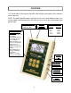
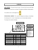
This section looks at the layout of the NIBP-1030 and gives descriptions of the elements
that are present.
NOTE: The NIBP-1030-BE model is different from the unit shown below in that it uses
universal patient lead banana posts that allow for the use of snaps and/or banana-type
patient leads.
OVERVIEW
Patient Lead Connectors:
Left Side Right Side
RA/R V2/C2
LA/L V3/C3
RL/N V4/C4
LL/F V5/C5
V1/C1 V6/C6
6 Light Touch Keys for
Selecting Parameters
and Settings:
POWER for Turning Unit
On and Off
UP and DOWN Arrows
for Scrolling Through
Selected Options.
(When No Options are
Selected, for Changing
Display Screen.)
SELECT for Choosing
Setting or Parameter to
Change
SETUP/RETURN for
Entering and Exiting
Setup Menu
RESET for resetting
peak pressure reading.
LCD Graphical Display:
Shows Test Data and
Configuration Data
Male Quick
Connect for
Pressure Input
Power
2.1 mm Jack,
7 pin Mini-Din
connector for
RS-232 or SpO
2
Simulation
8-Pin Mini-DIN
Plug Connector
for Temperature
Simulation
6 pin Mini-
Din
connector for
IBP
Simulation