
Instructions / Assembly

5
2
2
3
1
4
ASSEMBLY INSTRUCTIONS
READ ALL SAFETY WARNINGS & ASSEMBLY INSTRUCTIONS CAREFULLY BEFORE ASSEMBLING OR OPERATING
YOUR COOKER. Inspect contents in the box to ensure all parts are included and undamaged.
FOR MISSING PARTS OR ASSISTANCE, PLEASE CALL 1-800-864-6194 M-F 7:30am - 4:30pm CST.
Proof of purchase will be required.
TOOLS REQUIRED:
Adjustable Wrench
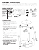
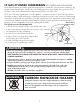
PARTS INCLUDED:
Model #KDS-144
Phillips Head
Screwdriver
1- Round Frame
3- Legs
3 - Long Bolts
7 - Locking Nuts
1 - Heat Shield
4 - Short Bolts
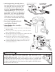
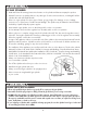
1. Remove components from the box and
packing. T
urn round frame upside down
as shown. Assemble cooker while in this
upside down position.
2. Mount Burner Support Bar - Line up holes
in support bar to the holes in the frame as
shown. Attach bolts and nuts as shown.
Wrench tighten.
3. Attach Burner and Heat Shield to
Support Bar -
A Remove locking nut from bottom of burner.
B. Turn burner upside down and position
as shown.
C. Insert the burner bolt through the burner
support bar.
D. Place heat shield over bolt.
E. Attach locking nut and wrench tighten.
4. Attach Legs to Base Frame - Slide legs on
frame to match holes. Insert and hand
tighten all bolts and nuts.
NOTE: You will wrench tighten leg bolts
at a later stage.
COOKER ASSEMBLY
1- 10 PSI Regulator
Hose Assembly
1- Stockpot
with Lid
1- Perforated Basket
1 - BG10 Burner
with Locking Nut
1- Air Shutter
with Screws
1 - Burner Support Bar
Hex Wrench,
provided