
Owner Manual

5
1 - Drain Valve with 2 Gaskets
1 - Hex Wrench
ASSEMBLY INSTRUCTIONS
READ ALL SAFETY WARNINGS & ASSEMBLY INSTRUCTIONS CAREFULLY BEFORE ASSEMBLING OR OPERATING
YOUR FRYER. Inspect contents in the box to ensure all parts are included and undamaged.
FOR MISSING PARTS OR ASSISTANCE, PLEASE CALL 1-800-864-6194 M-F 7:30am - 4:30pm CST.
Proof of purchase will be required.
TOOLS REQUIRED:
Adjustable Wrench
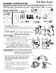
PARTS INCLUDED:
Model #700-701
1 - Fryer Body
2 - Stainless Steel Baskets
2 - Extension Legs
1 - Exhaust Vent
1 - Thermometer Wrench
1 - Thermometer
1 - Drain Hose
Thermometer Wrench,
provided
Hex Wrench, provided
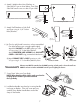
1. Slide Extension Leg into holes on the Fryer.
Attach using the 4 Large Hex Bolts/Washers/Nuts.
4. Lock Basket Handle into place by inserting handle
into loops on Basket. Then with some pressure,
carefully force Basket Handle Bars around the clasp
on the Basket.
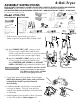
2. (a) Attach EXHAUST VENT to LEFT opening on back
of Fryer using 2 Long Hex Bolts/Washers/Nuts.
Check to verify that all connections on the pre-assembled
Gas Inlet/Jet Burner are screwed together tightly.
(b) Attach the GAS INLET to RIGHT opening on back
of Fryer using 4 Short Hex Bolts/Washers/Nuts.
Attach REGULATOR HOSE ASSEMBLY with GAS INLET
COVER to GAS INLET using pre-attached Hex Bolts/Nuts.
3. Screw Drain Valve onto Fryer Body. Wrench tighten.
NOTE: When Attaching Drain Valve, make sure that the
Locking Tab for Handle is positioned towards
the Fryer Body.
4 - Short Hex Bolts/Washers/Nuts
for Gas Inlet
4 - Large Hex Bolts/Washers/Nuts
for Extension Legs
(a)
ON LEFT
SIDE
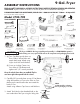
5. Attach Regulator Hose Assembly to Brass Connector
on Gas Inlet/Jet Burner. Refer to pages 8 - 9.
EXHAUST VENT
Exhaust vent MUST be attached to the LEFT
opening on back panel so that exhaust
flows AWAY from burner intake and AWAY
from the person lighting the burner.
WARNING
4-Gal. Fryer
(b)
ON RIGHT
SIDE
GAS INLET/JET BURNER
1- Regulator
Hose Assembly
with Gas Inlet Cover
1 - Gas Inlet/Jet Burner