
Owner`s manual


CHAPTER 2: COMPONENTS/SYSTEMS 7
Trophy Center Console •
Owner’s Manual Supplement
12-Volt DC System- Fuses, Circuit Breakers and Switches
The engine is protected by a large circuit breaker on the engine. The accessories on
some models are protected by a master circuit breaker usually located near the bat-
tery. A fuse block for branch accessory circuits is located near the helm panel.
Wires are color-coded to indicate which accessory each fuse services. Some items,
such as radios and bilge pumps, may be fused individually at the unit. Autofloat
switches are fused at the battery.
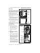
Some models are equipped
with a battery switch. Your
Sport Boat Owner’s Manual
provides a general descrip-
tion of battery switch func-
tion in the Batteries portion
of the Electrical Section.
Table 1: Battery Switch Positions
Battery
Switch
Position
Engine Starting
Accessories
and Lights
Engine
Alternator
POSITION
"1"
Battery "1"
Provides Starting Power
Provides Power
From Battery "1"
Charges
Battery "1"
POSITION
"2"
Battery "2"
Provides Starting Power
Provides Power
From Battery "2"
Charges
Battery "2"
"BOTH"
POSITION
Both Batteries
Provide Starting Power
Both Batteries Provide Accessory
Power (not advised unless
engine is running)
Charges
"BOTH"
Batteries
SHOCK & ELECTRICAL SYSTEM DAMAGE HAZARD!
• NEVER disconnect the battery cables while the engine is running since dam-
age may occur to your boat’s electrical system components.
• The parallel switch should be turned on only in emergencies.
• The battery charging systems (alternators and battery charger) are designed
to charge lead-acid batteries. Before installing gel-cell or other new technol-
ogy batteries, read and follow the battery charger’s operating instructions.
CAUTION!
!
POSITION "1"
BATTERY "1"
ACTIVATES
POSITION "2"
BATTERY "2"
ACTIVATES
POSITION "BOTH" ACTIVATES
BOTH BATTERIES
"OFF" POSITION
(ONLY BATTERY
IN SOME MODELS)
BATTERY
SWITCH