
Technical data


Installing a WAN Adapter Module
116273-A Rev. 00
4-7
4.
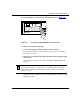
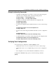
Using a Phillips screwdriver, insert and tighten the screw (Figure 4-5).
Figure 4-5. Securing the Adapter Module to the Front Panel
5.
Remove the antistatic wrist strap.
6.
Connect the appropriate WAN cabling to the new interface.
For cabling information, see the module-specific Supplement and the Bay
Networks Cable Guide.
7.
Turn power on, and check the diagnostic LEDs on the front panel of the
base module.
See “Powering On and Off” and “Understanding the ARN/DC LEDs” in
Chapter 3.
If the module fails its diagnostic test, the Fail LED remains on and the module
LED flashes rapidly.
Note:
For information about the LEDs on the newly installed module, see the
module-specific Supplement included in your upgrade kit. The new module’s
LEDs will not indicate data transfer until you have configured and enabled
software services.
ISDN
DSU/CSU
1
2
ARN0033A