
Technical data


Installing and Operating BayStack ARN/DC Routers
3-8
116273-B Rev 00
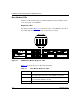
V.34 Modem LEDs
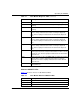
Table 3-12
describes the V.34 modem adapter module LEDs.
Ensuring a Successful Installation
After connecting the ARN/DC to the network, you can ensure a successful
installation by checking the diagnostic LEDs on the front panel of the base
module (refer to Figure 3-1 on page 3-2).
When you power on the ARN/DC, the following sequence of front panel LED
activity should occur:
• All base module LEDs light momentarily; this tests that the LEDs are
operational.
• The Run, Boot, and Fail LEDs count through a short, initial startup sequence.
• The Pwr (power) LED lights and remains on.
• The Run LED begins flashing and continues to flash until the ARN/DC
completes all diagnostic tests.
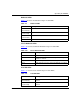
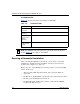
Table 3-12. V.34 Modem LEDs
LED Meaning
TX
(Transmit)
Lights when the interface transmits data over the network.
RX
(Receive)
Lights when the interface receives data from the network.
RLSD
(Received Line
Signal
Detection)
Lights when the modem activates.
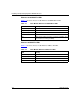
DTR
(Data Terminal
Ready)
Lights when the interface is ready to transmit data.
Note:
The ARN/DC back-panel supports an optional V.34 Console Modem
module. Table 3-12
also applies to these LEDs.