
Technical data


Installing and Operating BayStack ARN/DC Routers
3-6
116273-B Rev 00
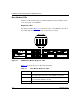
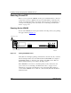
Adapter Module LEDs
When the ARN/DC has an optional serial, ISDN, 56/64K DSU/CSU, FE1/E1
DSU/CSU, FT1/T1 DSU/CSU, X.25 PAD, or V.34 modem adapter module
installed, its interface LEDs are visible on the front panel. For the location of the
two ARN/DC adapter module slots, see Figure 1-4 on page 1-9.
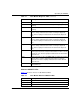
Serial LED
Table 3-7
describes the serial adapter module LED.
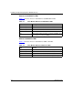
ISDN BRI LEDs (S/T or U Interfaces)
Table 3-8
describes the ISDN BRI adapter module LEDs.
Note:
The ARN/DC base module boots to a fully operational state before
bringing up adapter module interfaces.
Table 3-7. Serial LED
LED Meaning
RLSD Lights when Received Line Signal Detection (RLSD) is active on the
serial interface (COM1 or COM2).
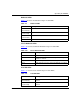
Table 3-8. ISDN BRI LEDs
LED Meaning
S/T Interface
Unlabeled LED Lights when the ARN/DC is using the D Channel.
U Interface
D (D-channel; 16 Kb/s management
channel)
Lights when the ARN/DC is using the D-channel.
DD
(Data Detect)
Lights when the interface detects a connection to
an external device such as a switch.
B1
(B-Channel #1; 64 Kb/s data channel)
Lights when the ARN/DC is using B Channel #1.
B2
(B-Channel #2; 64 Kb/s data channel)
Lights when the ARN/DC is using B Channel #2.