
Technical data


Installing and Operating BayStack ARN/DC Routers
3-2
116273-B Rev 00
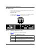
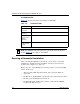
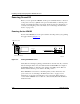
Base Module LEDs
The base module includes diagnostic LEDs and Ethernet interface LEDs, visible
on the front panel of the ARN/DC.
Diagnostic LEDs
The diagnostic LEDs (Figure 3-1
) indicate the status of the ARN/DC itself. All of
these LEDs light briefly when you turn on the DC power switch.
Figure 3-1. ARN/DC Base Module Diagnostic LEDs
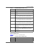
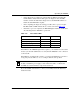
Table 3-1 describes the base module diagnostic LEDs.
Table 3-1. Base Module Diagnostic LEDs
LED Meaning
Run Flashes for 1 to 3 minutes, indicating that diagnostic tests are running.
When it lights again and remains on, the ARN/DC is operational.
Boot Lights for 1 to 3 minutes, indicating that diagnostic tests were
successful and the ARN/DC is booting.
Fail Lights again and remains on when diagnostic failure occurs.
(continued)
Run
Boot
Fail
Pwr
RPS
Fan
Base
Adapter1
Adapter2
Expansion
DCM
PCMCIA
ARN0059A
COM3 COM4 COM5
COM
U
D
DD
B1
B2
RLSD
Run
Boot
Diag
Pwr
RPS
Fan
Base
Adapter1
Adapter2
Expansion
DCM
PCMCIA
BayStack Advanced Remote Node
RLSD3
RLSD4
RLSD5
1
2
Serial
Serial
ISDN BRI
withNT1
Tx
Rx
Cl
Tx
Rx
Cl
10BaseT
AUI
Ethernet 1
10BaseT
AUI
Ethernet 2