
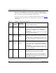
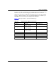
Technical data


Installing and Operating BayStack ARN/DC Routers
1-28
116273-B Rev 00
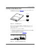
3.
Insert a slotted screwdriver through the opening in the front of the
protective casing that surrounds the terminal block to loosen the three
terminal block screws (Figure 1-20)
.
Do not remove the terminal block screws.
4.
Attach the minus lead (-48 VDC input) from the power source to the
_
terminal block (Figure 1-21)
.
Thread the leads through the opening at the top of the protective casing.
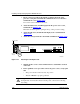
5.
Attach the plus lead (-48 VDC Return input) to the + terminal block
(Figure 1-21)
.
6.
Attach the earth ground lead to the middle terminal block (Figure 1-21).
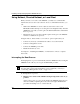
Figure 1-21. Attaching the DC Input Leads
7.
Tighten all three screws on the terminal block to establish the electrical
connection.
8.
Before qualified service personnel connect the power source, verify again
that
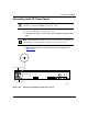
• The power switch is in the lowered, off position
• That the ARN/DC is properly grounded
Danger:
Once the ARN/DC is connected to the power source, do not remove
the input leads. You must disconnect from the power source before removing
any wiring.
ARN0082A
Console Modem
Redundant Power
+
_
3 prong cable
Power switch
OFF (0)
I
0