
Technical data


Installing and Operating BayStack ARN/DC Routers
1-14
116273-B Rev 00
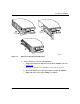
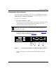
Figure 1-9. Connecting a Serial Cable to an Adapter Module Interface
Serial adapter modules, labeled COM, can be in position 1 or 2. These
interfaces are COM1 and COM2.
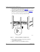
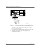
3.
Secure the cable to the interface using the capture screws on the cable.
4.
Connect the other end of the cable to the appropriate serial
communications equipment.
To
RS-232,
RS-422,
RS-530,
V.28,
V.35,
or X.21
interface
COM
U
D
DD
B1
B2
RLSD
ISDN BRI
withNT1
1
2
Tx
Rx
Cl
Tx
Rx
Cl
10BaseT
Ethernet 1
10BaseT
Ethernet 2
ARN0066A
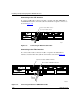
ARN
front
panel