
Technical data


Installing and Operating BayStack ARN/DC Routers
C-14
116273-B Rev 00
Service Modem Connections
The ARN/DC back panel contains one modem service interface, labeled Modem;
its DB-9 plug connector provides an RS-232-D serial connection. You use this
local console port to connect the ARN/DC to any Hayes compatible modem for
remote dial-in access.
The BayStack ARN/DC shipping package includes the console/modem kit
(Order No.110310) for connecting devices to the Modem port. To connect a
modem, use the cable (Order No.110307 from the kit), a standard, 15-foot molded
AT serial cable with DB-9 receptacle to DB-25 plug connectors.
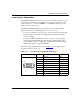
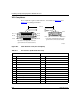
The connector pin assignment described in Table C-12
shows signal and pin
assignments for the modem port.
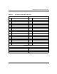
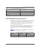
Table C-12. Service Modem Port DB-9 Pin Assignments
Pin Assignment Pin No. Signal Name Direction
1 DCD (Data carrier detect) From modem
2 TXD (Transmit data) To modem
3 RXD (Receive data) From modem
4 DSR (Data set ready) From modem
5 GND N/A
6 DTR (Data terminal ready) To modem
7 CTS (Clear to send) From modem
8 RTS (Request to send) To modem
9 Not used N/A
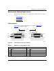
Pin 1
Pin 9